An electrochemical hydrogenation device and method

A hydrogenation device and electrochemical technology, applied in chemical instruments and methods, chemical/physical processes, chemical/physical/physicochemical processes, etc., can solve problems such as difficult product separation, excessive cathode water, and insufficient anode water. Achieve the effects of solving insufficient product yields, improving reaction efficiency, and solving product inhibition problems

Pending Publication Date: 2018-04-17
DALIAN UNIV OF TECH PANJIN INST OF IND TECH
View PDF5 Cites 2 Cited by
  • Summary
  • Abstract
  • Description
  • Claims
  • Application Information

AI Technical Summary

Problems solved by technology

[0007] Aiming at the problems of high temperature and high pressure energy consumption of conventional hydrogenation devices, and the problems of poor water management and difficult separation of products in conventional electrochemical hydrogenation devices, the present invention provides an anion-cation exchange membrane self-humidification at room temperature and pressure chemical hydrogenation method
The feature of this invention is that by using the anion and cation exchange membrane as the electrolyte at the same time, the movement direction of the water in the reactor is concentrated to point to the anion and cation electrolyte membrane layer interface, and the water generated in the electrolyte can be collected and reused to effectively solve the shortage of water in the anode and the amount of water in the cathode The problem of too large; by designing a membrane contactor to separate and recover products and reactants in situ, the problems of insufficient product yield and product inhibition are solved, and the reaction efficiency is improved

Method used


Image

  • An electrochemical hydrogenation device and method
  • An electrochemical hydrogenation device and method

Examples


Embodiment 1

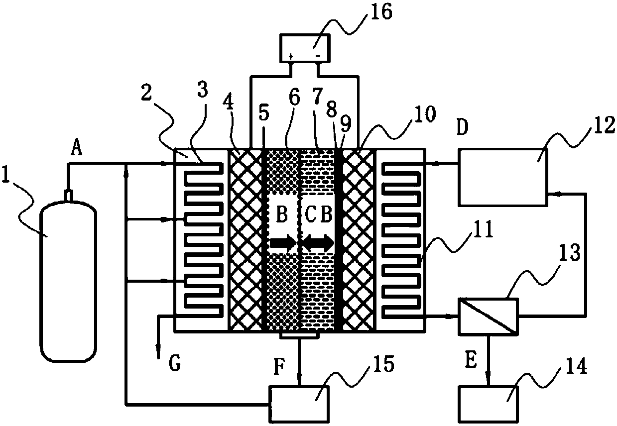
[0069] like figure 1 As shown, an electrochemical hydrogenation device, the device includes: a hydrogen storage tank 1, a reactor shell 2, a hydrogen flow channel 3, a hydrogen diffusion layer 4, a hydrogen dissociation catalytic layer 5, a cationic electrolyte membrane layer 6, an anion Electrolyte membrane layer 7, water dissociation catalytic layer 8, hydrogenation catalytic layer 9, hydrogenation diffusion layer 10, hydrogenation reactant flow channel 11, hydrogenation reactant storage tank 12, product separator 13, hydrogenation product storage tank 14, Ultrasonic humidifier 15, power supply 16,

[0070]The outlet of the hydrogen storage tank 1 is connected to the inlet of the hydrogen flow channel 3, one side of the hydrogen flow channel 3 is connected to one side of the hydrogen diffusion layer 4, the other side of the hydrogen diffusion layer 4 is connected to the hydrogen dissociation catalytic layer 5, and the hydrogen dissociation catalytic layer 5 The other side i...

Embodiment 2

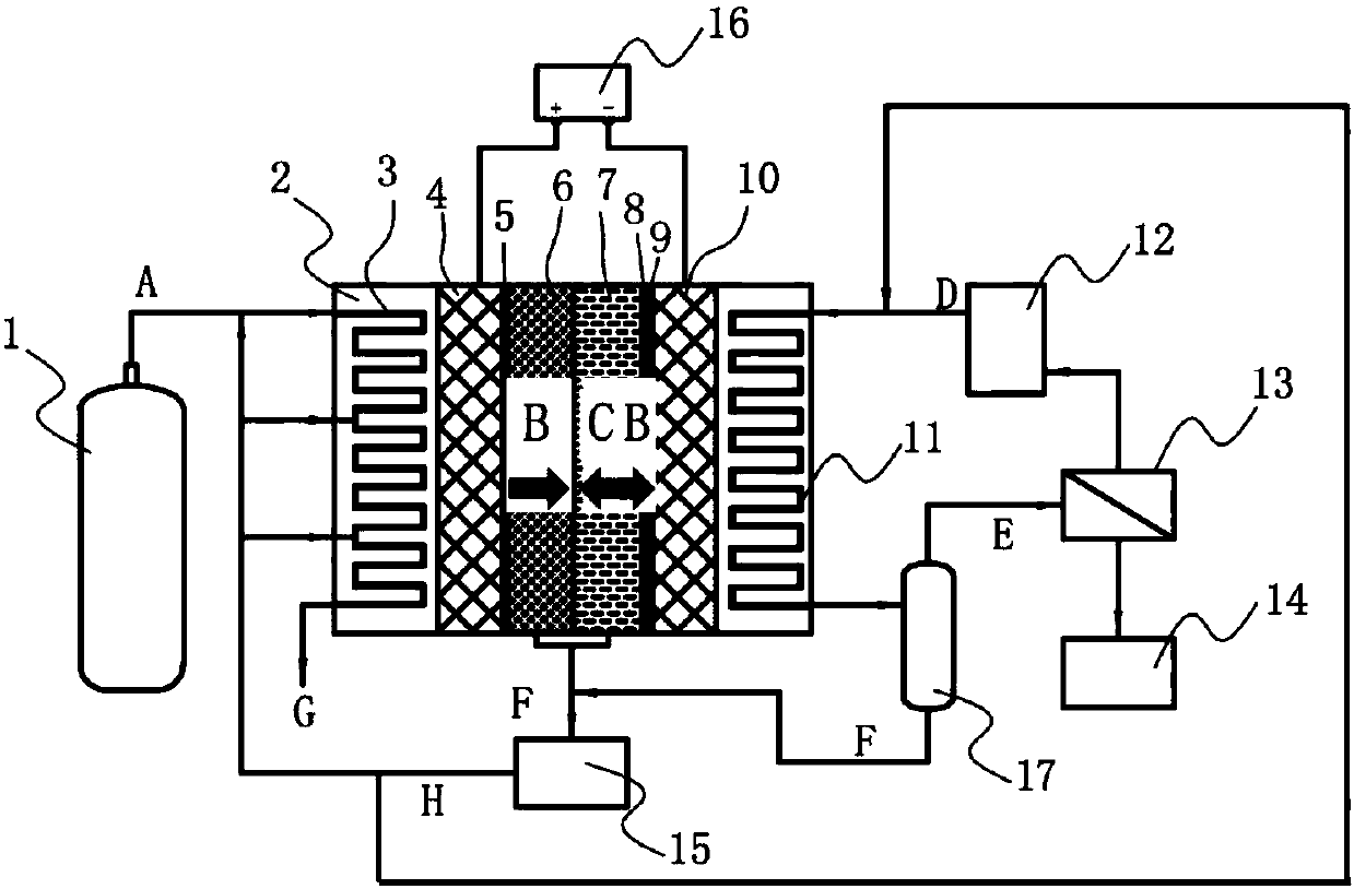
[0075] Such as figure 2 As shown, an electrochemical hydrogenation device, the device includes: a hydrogen storage tank 1, a reactor shell 2, a hydrogen flow channel 3, a hydrogen diffusion layer 4, a hydrogen dissociation catalytic layer 5, a cationic electrolyte membrane layer 6, an anion Electrolyte membrane layer 7, water dissociation catalytic layer 8, hydrogenation catalytic layer 9, hydrogenation diffusion layer 10, hydrogenation reactant flow channel 11, hydrogenation reactant storage tank 12, product separator 13, hydrogenation product storage tank 14, Ultrasonic humidifier 15, power supply 16, hydrogenation product separatory tank 17,

[0076] The outlet of the hydrogen storage tank 1 is connected to the inlet of the hydrogen flow channel 3, one side of the hydrogen flow channel 3 is connected to one side of the hydrogen diffusion layer 4, the other side of the hydrogen diffusion layer 4 is connected to the hydrogen dissociation catalytic layer 5, and the hydrogen d...


PUM

PropertyMeasurementUnit
Particle sizeaaaaaaaaaa

Abstract

The invention relates to an electrochemical hydrogenation device and method and belongs to the technical field of chemical engineering. The device includes a planar laminated assembly. The planar laminated assembly is formed by laminating a hydrogen dissociation catalytic layer, a cation electrolyte membrane layer, an anion electrolyte membrane layer, a water dissociation catalytic layer and a hydrogenation catalytic layer which are planar layers in order. When the device is utilized to perform hydrogenation, the reaction process is stable and controllable, the reaction yield is high, a reactor is self-humidifying, and water management is easy to perform. The device and the method allow a hydrogenation process to be efficient, rapid and stable, do not need high temperature or high pressure, only consume a small amount of electricity, and can perform a catalytic hydrogenation reaction on organic matters at room temperature under atmospheric pressure. A reaction process is economical andenvironmentally friendly.

Description

technical field [0001] The invention relates to an electrochemical hydrogenation device and method, belonging to the technical field of chemical industry. Background technique [0002] Hydrogenation reaction is an important process technology in chemical production process. Straight-run gasoline, diesel, jet fuel and other oil products usually need hydrogenation reaction to remove sulfur, nitrogen, etc.; biomass diesel generally has the problem of high oxygen content, and the quality of biomass oil can be effectively improved by hydrogenation treatment. Due to the low activity of the hydrogenation reaction, a higher pressure is usually required to maintain the partial pressure of hydrogen to make the reaction proceed forward. At present, the conventional hydrogenation method needs to use a high-temperature and high-pressure reactor to carry out the hydrogenation reaction under the conditions of 6-18MPa and 350-450°C. The relatively harsh reaction conditions require complex...

Claims


Application Information

Patent Timeline
IPC IPC(8): B01J19/08B01J19/00
CPCB01J19/0006B01J19/0053B01J19/087B01J2219/0892
Inventor 代岩贺高红
Owner DALIAN UNIV OF TECH PANJIN INST OF IND TECH
Why Eureka
Try Eureka