
Method and device for optimal operation control of boiler heater

A technology for optimizing operation and control methods, applied in the direction of controlling combustion, combustion methods, indirect carbon dioxide emission reduction, etc., can solve problems such as large steam consumption, unconsidered air preheater blockage, increased coal consumption of heater power generation, etc., and achieve thermal efficiency High efficiency, guaranteed operation economy and guaranteed equipment safety

Active Publication Date: 2019-03-22
STATE GRID HEBEI ENERGY TECH SERVICE CO LTD +3
View PDF5 Cites 0 Cited by
  • Summary
  • Abstract
  • Description
  • Claims
  • Application Information

AI Technical Summary

Problems solved by technology

During operation, the outlet air temperature of the heater is controlled at a certain set value by adjusting the steam intake, but the current set value for the outlet air temperature is only an empirical value, usually the control is relatively high, and the denitrification device is not considered due to the operation Causes the blockage of the air preheater, resulting in unreasonable operation of the air heater, which not only consumes a large amount of steam, but also reduces the thermal efficiency of the boiler, resulting in an increase in the coal consumption of the unit for power generation
Some research results have shown that unreasonable operation of the heater can increase the coal consumption of the unit for power generation by 2-3g / KWh

Method used


Image

  • Method and device for optimal operation control of boiler heater
  • Method and device for optimal operation control of boiler heater
  • Method and device for optimal operation control of boiler heater

Examples


Embodiment Construction

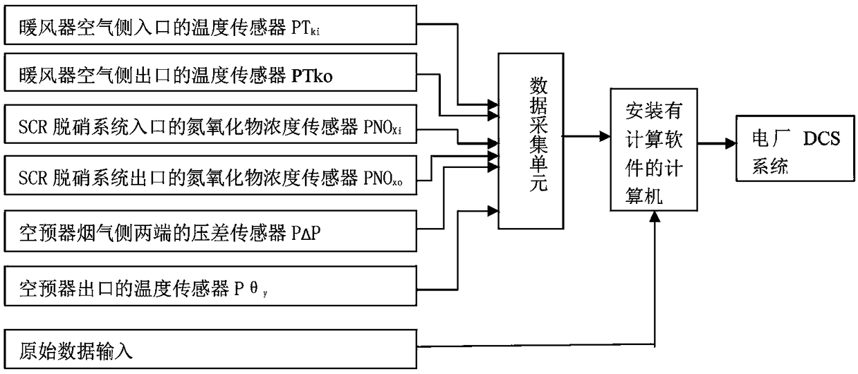
[0029] A boiler heater optimization operation control device, including a temperature sensor PT installed at the air side inlet of the boiler heater ki , The temperature sensor PT installed at the air side outlet of the heater ko , The nitrogen oxide concentration sensor PNO installed at the inlet of the boiler SCR denitrification system Xi , The nitrogen oxide concentration sensor PNO installed at the outlet of the boiler SCR denitrification system Xo, The differential pressure sensor PΔP installed at both ends of the flue gas side of the boiler air preheater, the temperature sensor Pθ installed at the outlet of the flue gas side of the air preheater y , a data acquisition unit and a computer with Visual Basic software installed; the temperature sensor PT ko , temperature sensor PT ki , Nitrogen oxide concentration sensor PNO Xi , Nitrogen oxide concentration sensor PNO Xo , differential pressure sensor PΔP and temperature sensor Pθ y The output ends of the data acquisi...


PUM


Abstract

A boiler air heater optimizing operation control device comprises a temperature sensor PTki installed on an air side inlet of a boiler air heater, a temperature sensor PTko installed on an air side outlet of the air heater, an oxynitride concentration sensor PNOXi installed on an inlet of a boiler SCR denitration system, an oxynitride concentration sensor PNOXo installed on an outlet of the boilerSCR denitration system, differential pressure transducers P delta P installed at the two ends of the smoke side of a boiler air pre-heater, a temperature sensor P theta y installed on an outlet of the smoke side of the air pre-heater, a data acquiring unit and a computer provided with Visual Basic software. According to the boiler air heater optimizing operation control device, the oxynitride concentration on the inlet of the SCR denitration system, the oxynitride concentration on the outlet of the SCR denitration system, the differential pressure on the smoke side of the air pre-heater and other parameters are introduced, the factor that air pre-heater is blocked by running of the denitration system and the too high ammonia escaping rate is taken into consideration and serves as anotherinput parameter for controlling the steam inlet amount of the air heater, the air temperature on the outlet of the air heater is properly raised, so that hydrogen sulfate generated by the denitrationsystem is not prone to congealing on the heat exchanging face of the air pre-heater, and blockage of the air pre-heater is prevented.

Description

technical field [0001] The invention relates to a method and device for controlling the optimal operation of a boiler heater, more specifically, to a method and device for controlling the operation of a heater that can prevent corrosion and blockage of a boiler air preheater and optimize boiler operation. Background technique [0002] The boiler heater is a heat exchanger that uses the low-pressure extraction steam of the steam turbine to heat the inlet air of the air preheater. The boiler heater is installed between the outlet of the blower and the inlet of the air preheater, so it is also called a front air preheater. A heater is added to increase the temperature of the air entering the air preheater and the wall temperature of the air preheater, thereby preventing low-temperature corrosion. After using the air heater, the heat transfer temperature difference of the air preheater is reduced, the exhaust gas temperature of the boiler is also increased, and the thermal effi...

Claims


Application Information

Patent Timeline
Patent Type & Authority Patents(China)
IPC IPC(8): F23L15/04F23N5/00F23N5/02
CPCF23L15/04F23N5/003F23N5/02Y02E20/34
Inventor 张勇胜张万德马登卿闫慧博贾永会刘文献
Owner STATE GRID HEBEI ENERGY TECH SERVICE CO LTD
Learn More