Floor ground heating device and installing method thereof

A floor and floor heating technology, which is applied in the field of floor heating devices, can solve the problems of non-environmental protection, waste of energy, waste of materials, etc., and achieve the effects of prolonging service life, saving energy, and preventing deformation

Inactive Publication Date: 2018-04-13
NINGBO ZHENHAI JIEDENG APPL TECH INST
View PDF7 Cites 0 Cited by
  • Summary
  • Abstract
  • Description
  • Claims
  • Application Information

AI Technical Summary

Problems solved by technology

[0003] With the improvement of people's living standards, more and more people install underfloor heating. At present, underfloor heating on the market mainly includes water heating and electric heating, but they are all installed under the floor and covered with cement. The thermal conductivity is also poor, so the underfloor heating cannot reach the predetermined temperature even if it is turned on for a day. In winter, it can only be turned on every day, even if there is no one at home at work, and occasionally when the weather is warmer, it will cause a lot of waste of energy. Underfloor heating has a large temperature difference between the upper and lower floors, and requires high floor materials. Generally, deformation will occur. Most of the boards are sawed into three or more layers and glued together. This is not only a waste of materials, but also not environmentally friendly. Of course, there are Another type of floor heating device is to saw the floor into upper and lower layers, and install the carbon fiber heating wire between the upper and lower layers of the floor, so that the heating effect is relatively good, but the manufacturing process is much troublesome.

Method used


Image

  • Floor ground heating device and installing method thereof

Examples


Embodiment example 1

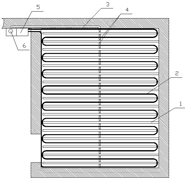
[0016] Implementation case one; a floor heating device, including a floor, a ground ridge 1, a heater 5 and a heating body 2. A heating body 2 is provided between the ground ridge 1 and the ground ridge 1, and the heating body 2 is connected to the heater 5 to heat The body 2 is provided with at least one jet pipe 3 in the vertical direction, the heater 5 is a water heater, and the heating body 2 is a hot water pipe. The jet pipe 3 is provided with jet holes 4 on both sides of the hot water pipe, and one end of the jet pipe 3 is connected with Blower 6, the other end is blocked; when installing, slot the floor where the jet pipe 3 is laid, so that the jet pipe 3 is level with the floor, and then lay the ground ridge 1 according to the requirements of the floor, such as the jet pipe 3 above the ground The ground ridge 1 is slotted at the intersection with the jet pipe 3. If the jet pipe 3 is already level with the ground when laying, the ground ridge 1 does not need to be grooved...

Embodiment example 2

[0017] Implementation case two; other things are the same as above, heater 5 is an electric heater, heating body 2 is a silica gel heating belt or carbon fiber heating belt, or there is no gap between the floor and the wall, the floor and the skirting, which can also achieve rapid heating and The effect of underfloor heating.


PUM


Abstract

Disclosed is a floor ground heating device. The floor ground heating device comprises a floor, sleeper walls, a heater and a heating body. The floor ground heating device is characterized in that theheating body is arranged between the sleeper walls and connected with the heater, the heating body is provided with at least one air spraying pipe in the perpendicular direction of the heating body, and the air spraying pipe is arranged below the floor; heat generated by the heating body is blown to the position above the floor from the position below the floor through gaps between the floor and awall body as well as between the floor and a skirting line, so that circulation of indoor air is generated, and in this way, the purpose of rapid heating can be achieved; when the temperature reachesa set temperature, an air blower can slow down or stop working, and the heat generated by the heating body can continuously be transmitted upwards through the floor and the gap between the floor andthe skirting line; ventilating is conducted frequently below the floor, and the service life of the floor can be prolonged, so that the humidity of air above and the humidity of air below the floor are the same basically, and deformation of the floor is prevented; and the floor ground heating device can be closed when no one is at home and heating is not needed, and in this way, not only are energy sources saved greatly, but also requirements for the floor are reduced.

Description

[0001] Technical field [0002] The invention relates to a floor heating device, in particular to a floor heating device and an installation method thereof. Background technique [0003] With the improvement of people’s living standards, more and more people install underfloor heating. At present, underfloor heating on the market is mainly water heating and electric heating, but they are installed under the floor and covered with cement. The thermal conductivity is poor, so the floor heating can't reach the predetermined temperature for a day. In winter, it can only be turned on every day. Nobody at work also needs to turn it on. Occasionally, the weather is warm. This will cause a lot of waste of energy. The floor heating floor has a large temperature difference between the upper and lower floors. The floor material is required to be high. Generally, it will deform. Most of the wood boards are sawn into three or more layers and glued together. This is not only a waste of mate...

Claims


Application Information

Patent Timeline
Patent Type & Authority Applications(China)
IPC IPC(8): E04F15/02E04G21/14F24D3/14F24D13/02
CPCE04F15/02E04G21/14F24D3/142F24D13/024
Inventor 陈兆红
Owner NINGBO ZHENHAI JIEDENG APPL TECH INST
Why Eureka
Try Eureka