
Ball mill packing and sealing device

A packing sealing and sealing device technology, applied in the field of ball mills, can solve the problems of increasing the gap between the end cover hole and the rotating shaft, unavoidable oil leakage, and ineffective throttle grooves, so as to reduce wear, save costs, The effect of reducing energy consumption

Inactive Publication Date: 2018-04-13
ANHUI UNIVERSITY OF TECHNOLOGY AND SCIENCE
View PDF8 Cites 2 Cited by
  • Summary
  • Abstract
  • Description
  • Claims
  • Application Information

AI Technical Summary

Problems solved by technology

[0003] (1) Felt sealing device, the structure is relatively simple, but it is very easy to wear, and it cannot be compensated after wear, resulting in oil leakage, which will gradually increase until the next maintenance;
[0004] (2) The contact sealing device is simple to manufacture and install, and is easy to maintain. However, after a period of operation, the skeleton oil seal wears out, and the gap between the end cover hole and the rotating shaft increases, resulting in the throttle groove not working and easily causing leakage;
[0005] (3) The labyrinth seal is a non-contact seal. The labyrinth groove is set inside it to prevent a large amount of oil from leaking through the groove when the oil is running at high speed. gap, a small amount of oil leakage cannot be avoided, and it is easy for external dust to enter the equipment, causing wear and tear

Method used


Image

  • Ball mill packing and sealing device
  • Ball mill packing and sealing device

Examples


Embodiment

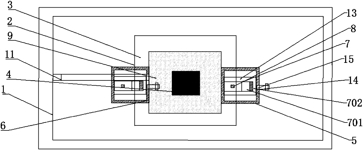
[0025] Such as figure 1 and figure 2 As shown, the present invention provides a packing sealing device for a ball mill, including a casing 1, the casing 1 is a cuboid box structure with an opening facing upwards, and a packing device 2 is installed at an upper position inside the casing 1, and the packing The device 2 includes a feed hopper 3 and a feed barrel 4. The feed hopper 3 is located at the opening of the cabinet 1 and has a trapezoidal cross section. At the feed port; the inside of the cabinet 1 is also equipped with a sealing device 5, the sealing device 5 is sleeved on the outer surface of the feeding cylinder 4, the sealing device 5 includes a sealing seat 6, the overall appearance of the sealing seat 6 It is a cuboid, and the center of the sealing seat 6 is dug with a through hole. The inner diameter of the through hole of the sealing seat 6 matches the outer diameter of the end of the feeding barrel 4. The sealing seat 6 is sleeved on the outer surface of the f...


PUM


Abstract

The invention discloses a ball mill packing and sealing device. The ball mill packing and sealing device comprises a machine box, a packing device is installed at the position, close to the upper portion, of the interior of the machine box, and the packing device comprises a feeding hopper and a feeding barrel. The feeding hopper is located at the opening position of the machine box, and the section of the feeding hopper is in a trapezoidal shape. The feeding barrel is a cylindrical barrel and embedded in the discharging opening position of the bottom of the feeding hopper in a sleeving mode.The interior of the machine box is further provided with a sealing device. The sealing device comprises a sealing seat. The sealing seat is connected with the outer surface of the feeding barrel in asleeving mode. A magnetic sealing assembly is connected with the tail end of a through hole of the sealing seat in a sleeving mode. The magnetic sealing assembly faces the tail end of the feeding barrel directly and is used for achieving bottom sealing of the feeding barrel. A circular-annular O-shaped ring is arranged at the connection of the magnetic sealing assembly and the sealing seat in a padded mode. A blowing-removing device is further installed on the lower portion of the interior of the machine box. The blowing-removing device is installed on the right side edge of an outlet of the feeding barrel. The ball mill packing and sealing device is good in sealing performance and is not prone to being worn, dust can also be effectively prevented from entering, the service life is prolonged, and the maintenance cost of equipment is reduced.

Description

technical field [0001] The invention relates to the technical field of ball mills, in particular to a ball mill packing sealing device. Background technique [0002] Ball mill is the key equipment for crushing materials after being crushed. It is mainly used in cement, silicate products, new building materials, refractory materials, chemical fertilizers, black and non-ferrous metal beneficiation, glass ceramics and other production industries. The poor sealing of the stuffing box between the inlet and outlet journal of the ball mill and the connecting pipeline has been a problem that has plagued the manufacturer for many years. There are mainly three sealing methods in today's ball mill packing sealing device, but each has the following disadvantages: [0003] (1) Felt sealing device, the structure is relatively simple, but it is very easy to wear, and it cannot be compensated after wear, resulting in oil leakage, which will gradually increase until the next maintenance; ...

Claims


Application Information

Patent Timeline
IPC IPC(8): B02C17/18
CPCB02C17/183B02C17/18
Inventor 张小龙苗润泽杨国太
Owner ANHUI UNIVERSITY OF TECHNOLOGY AND SCIENCE
Learn More