
Shell and Tube Heat Exchanger

A shell-and-tube heat exchanger and heat exchanger technology, applied in the field of nuclear power, can solve the problems of large fluid pressure drop along the process, flow dead zone of baffle plate, and reduce heat exchange efficiency, etc., so as to reduce the resistance along the process, Effect of reducing lateral impact and increasing applicability

Active Publication Date: 2019-10-15
CHINA NUCLEAR POWER DESIGN COMPANY +2
View PDF10 Cites 1 Cited by
  • Summary
  • Abstract
  • Description
  • Claims
  • Application Information

AI Technical Summary

Problems solved by technology

[0002] At present, the existing shell-and-tube heat exchangers with bow-shaped baffles have the following problems: 1) The bow-shaped baffles cause high-speed fluid to sweep across the heat exchange tube bundle, which is easy to induce vibration; 2) There is a flow dead zone in the baffles, which reduces the 3) The baffles make the fluid vertically impact the shell wall and cause a large pressure drop along the way
[0003] In order to overcome the shortcomings of the existing bow-shaped baffle plate shell-and-tube heat exchanger, the prior art uses a baffle rod shell-and-tube heat exchanger, and the baffle rod shell-and-tube heat exchanger arranges the baffle rods in the heat exchanger On the same cross-section of the same cross-section, although the flow resistance and leakage flow are reduced to a certain extent, the above-mentioned baffle rod heat exchanger is completely a vertical flow heat exchanger, and the heat exchange efficiency can still be improved.

Method used


Image

  • Shell and Tube Heat Exchanger
  • Shell and Tube Heat Exchanger
  • Shell and Tube Heat Exchanger

Examples


Embodiment Construction

[0027] In order to make the purpose of the invention, technical solution and beneficial technical effects of the present invention clearer, the present invention will be further described in detail below in conjunction with the accompanying drawings and specific implementation methods. It should be understood that the specific implementations described in this specification are only for explaining the present invention, not for limiting the present invention.

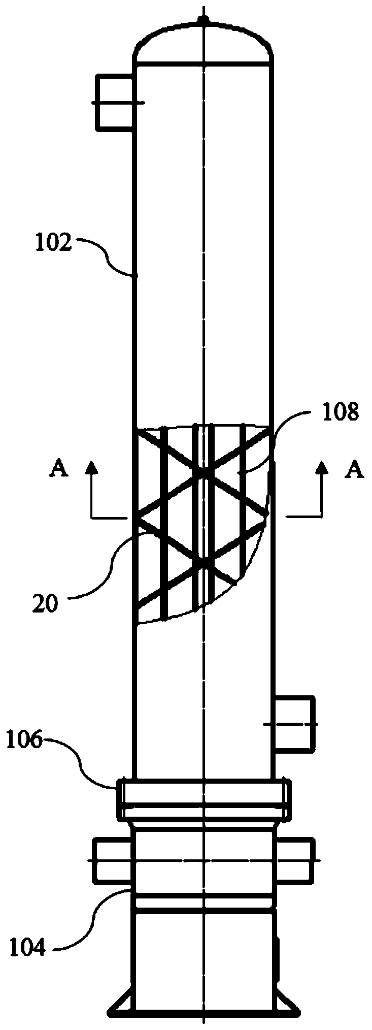
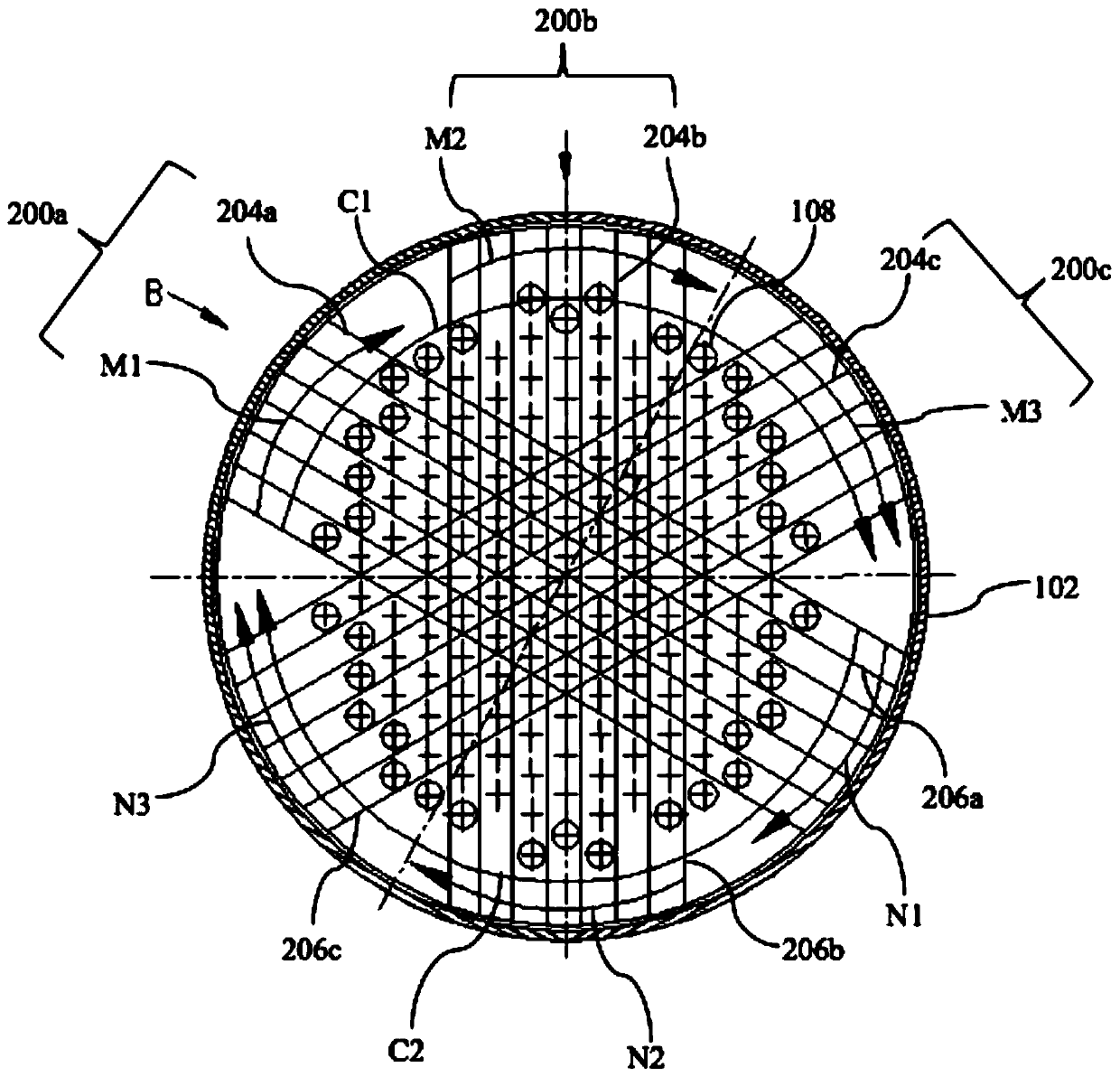
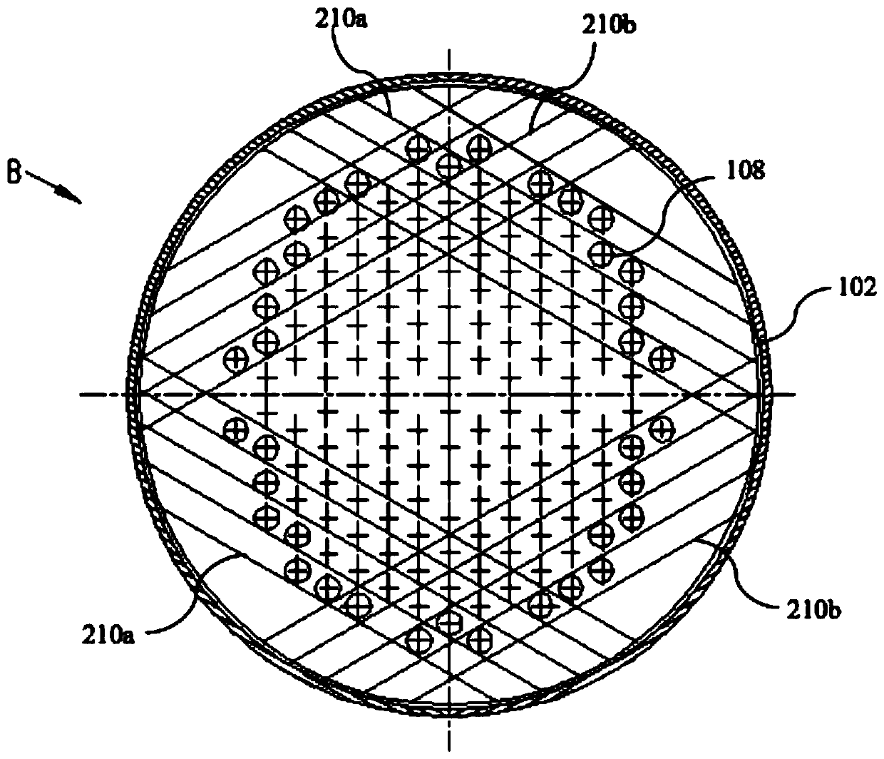
[0028] see Figure 1 to Figure 8 As shown, the shell-and-tube heat exchanger of the present invention includes a shell-side cylinder 102, a tube box cylinder 104, a tube sheet 106, and a heat exchange tube 108. The heat exchange tube 108 is fixed to the tube sheet 106 and the main body is arranged on the shell-side cylinder. In 102, a baffle rod assembly 20 is arranged in the shell-side cylinder 102, and the baffle rod assembly 20 includes a plurality of first baffle rods 200, and adjacent first baffle rods 200 are loca...


PUM


Abstract

The invention discloses a pipe-shell-type heat exchanger. The pipe-shell-type heat exchanger comprises a shell-side cylinder body, a pipe-box cylinder body, a pipe plate and a heat exchanging pipe. The heat exchanging pipe is fixed to the pipe plate, and a main body of the heat exchanging pipe is arranged in the shell-side cylinder body. A baffling rod assembly is arranged in the shell-side cylinder body and comprises a plurality of first baffling rods and a plurality of second baffling rods. Each first baffling rod comprises a connecting part, a first baffling part and a second baffling part,wherein the first baffling part and the second baffling part are connected with the two ends of the connecting part correspondingly. The first baffling rods are used for forming a double helix flow channel. Compared with the prior art, the pipe-shell-type heat exchanger has the following advantages that a shell-side fluid is arranged along with the first baffling rods and forms a double helix flow on the shell side, thus the shell-side fluid rotates and flushes a heat exchanging pipe bundle along with the double helix flow channel formed between the first baffling rods while passing through the first baffling rods and obliquely skimming over the heat exchanging pipe, the effect of heat transfer enhancing is improved, isochronous flow dead zones of the bow-shaped baffling rods are reduced,and the heat exchanging effect is enhanced.

Description

technical field [0001] The invention belongs to the technical field of nuclear power, more specifically, the invention relates to a shell-and-tube heat exchanger used in industrial sectors such as nuclear energy and nuclear power. Background technique [0002] At present, the existing shell-and-tube heat exchangers with bow-shaped baffles have the following problems: 1) The bow-shaped baffles cause high-speed fluid to sweep across the heat exchange tube bundle, which is easy to induce vibration; 2) There is a flow dead zone in the baffles, which reduces the 3) The baffles make the fluid vertically impact the shell wall and cause a large pressure drop along the way. [0003] In order to overcome the shortcomings of the existing bow-shaped baffle plate shell-and-tube heat exchanger, the prior art uses a baffle rod shell-and-tube heat exchanger, and the baffle rod shell-and-tube heat exchanger arranges the baffle rods in the heat exchanger Although the flow resistance and leak...

Claims


Application Information

Patent Timeline
Patent Type & Authority Patents(China)
IPC IPC(8): F28F9/24F28F9/02F28D7/16F28F19/00
Inventor 叶泉流陈兴江
Owner CHINA NUCLEAR POWER DESIGN COMPANY
Learn More