Electric hydraulic reversing valve core

A technology of hydraulic reversing valve and valve core, applied in the field of hydraulic reversing valve, can solve the problems of inability to realize automatic operation, large frictional resistance of valve core, large impact force of valve core, etc., achieve small friction force, reduce movement impact, smooth work effect

Pending Publication Date: 2018-04-06
LIMING HYDRAULIC CO LTD
View PDF0 Cites 0 Cited by
  • Summary
  • Abstract
  • Description
  • Claims
  • Application Information

AI Technical Summary

Problems solved by technology

[0003] Most of the existing hydraulic reversing valves control the hydraulic valve spool to move linearly in the valve hole through manual, motorized or electromagnetic valves, so as to achieve the purpose of changing the direction of hydraulic oil and the opening of the oil port to control the flow of the hydraulic valve; There are disadvantages such as inconvenient operation, automatic operation cannot be realized, and the valve core suffers from large frictional resistance when reversing, and the valve core has a large impact force under the action of external force, etc.

Method used


Image

  • Electric hydraulic reversing valve core
  • Electric hydraulic reversing valve core
  • Electric hydraulic reversing valve core

Examples


Embodiment Construction

[0030] The following will clearly and completely describe the technical solutions in the embodiments of the present invention with reference to the accompanying drawings in the embodiments of the present invention. Obviously, the described embodiments are only some, not all, embodiments of the present invention. Based on the embodiments of the present invention, all other embodiments obtained by persons of ordinary skill in the art without making creative efforts belong to the protection scope of the present invention.

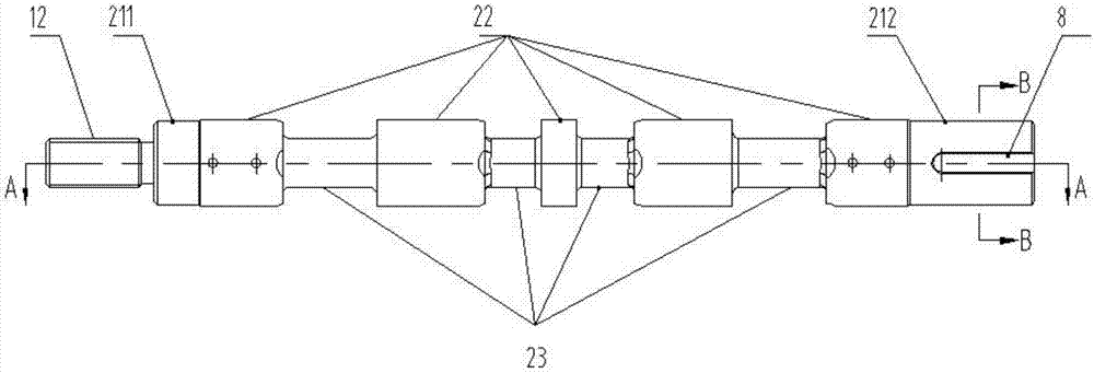
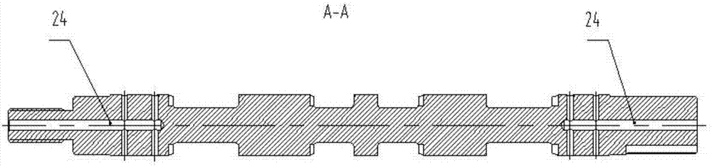
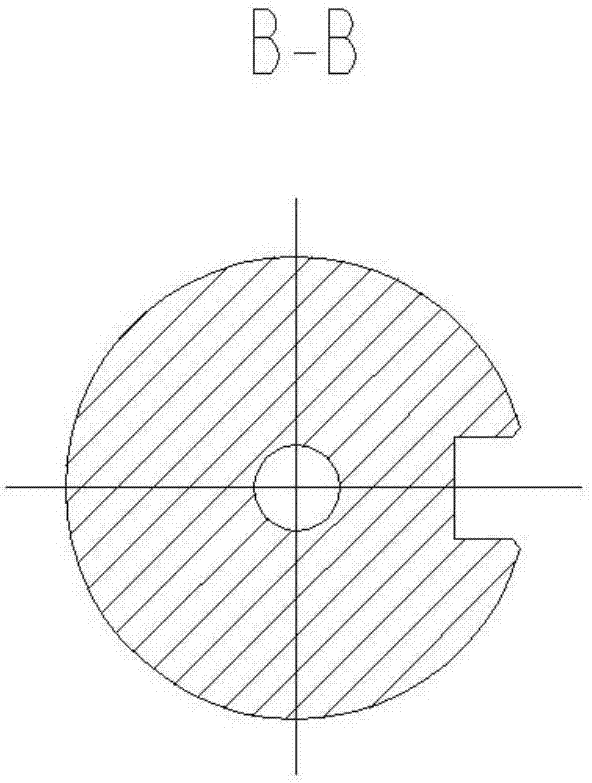
[0031] By improving the structure of the hydraulic valve, the present invention realizes the automatic operation of the hydraulic reversing valve, overcomes the shortcomings of the original hydraulic valve, such as large frictional resistance and large movement impact when reversing, and at the same time ensures that the electrohydraulic reversing valve Both ends of the spool are in the non-pressure zone, and the bearings are rotationally lubricated. Therefore...


PUM


Abstract

The invention discloses an electric hydraulic reversing valve core. The electric hydraulic reversing valve core comprises a connecting structure, a plurality of buffering structures located at one endof the connecting structure and valve core working sections arranged between the buffering structures; the connecting structure comprises a valve core screw rod, and the valve core screw rod is arranged at one end of the electric hydraulic reversing valve core; each buffering structure comprises a first pressure buffering section and a second pressure buffering section; and the valve core screw rod is sequentially connected with the first pressure buffering sections, the valve core working sections and the second pressure buffering sections. The electric hydraulic reversing valve core has theadvantages that by improving an original hydraulic reversing valve structure, automatic operation can be realized, the friction resistance is small, and movement impact is small, and the electric hydraulic reversing valve core has wide development and application prospects.

Description

technical field [0001] The invention relates to the technical field of hydraulic reversing valves, in particular to an electrohydraulic reversing valve spool. Background technique [0002] The hydraulic reversing valve is the key core component in the industrial control hydraulic system. It controls the direction and flow of the hydraulic actuator cylinder and the forward and reverse of the hydraulic motor. [0003] Most of the existing hydraulic reversing valves control the hydraulic valve spool to move linearly in the valve hole through manual, motorized or electromagnetic valves, so as to achieve the purpose of changing the direction of hydraulic oil and the opening of the oil port to control the flow of the hydraulic valve; There are disadvantages such as inconvenient operation, automatic operation cannot be realized, and the valve core suffers from large frictional resistance when reversing, and the valve core has a large impact force under the action of external force....

Claims


Application Information

Patent Timeline
Patent Type & Authority Applications(China)
IPC IPC(8): F16K11/07F16K31/04F16K31/50F16K3/314F16K3/36F16K47/00F15B13/02
CPCF15B13/02F16K3/314F16K3/36F16K11/0716F16K31/047F16K31/50F16K47/00
Inventor 梁富春叶萍
Owner LIMING HYDRAULIC CO LTD
Why Eureka
Try Eureka