Rail transmit conductor rail compensation device

A compensation device and rail transit technology, applied in the direction of power rails, etc., to achieve the effect of accurate guidance, good electrical conductivity, and free left and right expansion

Inactive Publication Date: 2018-04-06
ZHENJIANG DAQO SECHERON TRACTION POWER
View PDF7 Cites 0 Cited by
  • Summary
  • Abstract
  • Description
  • Claims
  • Application Information

AI Technical Summary

Problems solved by technology

Electrochemical corrosion should not occur between the parts

Method used


Image

  • Rail transmit conductor rail compensation device
  • Rail transmit conductor rail compensation device
  • Rail transmit conductor rail compensation device

Examples


Embodiment Construction

[0030] The present invention is described in further detail now in conjunction with accompanying drawing. These drawings are all simplified schematic diagrams, which only illustrate the basic structure of the present invention in a schematic manner, so they only show the configurations related to the present invention.

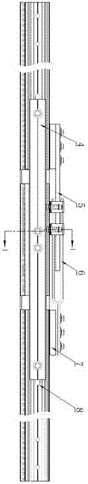
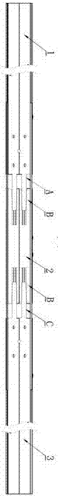
[0031] Such as figure 1 , image 3 , Figure 4 and Figure 6 As shown, the present invention is a rail transit conductive rail compensation device for a steel-aluminum composite rail power supply system in urban rail transit, which includes a left slide rail, a middle rail, a right slide rail, an anchor splint, a current connector main piece, a current Connector sub-sheets, transfer pads; such as figure 2, the right end of the left slide rail is provided with a plug-in mechanism A, the two ends of the middle rail are provided with a plug-in mechanism B, and the left end of the right slide rail is provided with a plug-in mechanism C, and the plug-in mechan...


PUM


Abstract

The invention relates to a rail transmit conductor rail compensation device which includes a left sliding rail, a middle sliding rail, a right sliding rail, anchoring clamping plates, a current connector main slice, a current connector auxiliary slice and a changeover backing plate. The right end face of the left sliding rail is provided with an insertion connection mechanism A, the two end facesof the middle sliding rail are provided with insertion connection mechanisms B, the left end face of the right sliding rail is provided with an insertion connection mechanism C, the insertion connection mechanism is in insertion connection with the insertion connection mechanism B through a gear shaping structure, and the insertion connection mechanism C is in insertion connection with the insertion connection mechanism B through a gear shaping structure. The left sliding rail and the right sliding rail are provided with long holes, the middle sliding rail is provided with fixing holes, the anchoring clamping plates are mounted on the two sides of the left sliding rail, the middle sliding rail and the right sliding rail through connecting pieces, the long holes and the fixing holes, and the anchoring clamping plates are fixedly connected with the middle sliding rail and slidably connected with the left sliding rail and the right sliding rail. The current connector main slice is fixedlyconnected to the upper end face of the left sliding rail through a conductive part, the current connector auxiliary slice is connected to the upper end face of the right sliding rail through a conductive part, and the main slice is slidably connected with the auxiliary slice.

Description

technical field [0001] The invention relates to a rail transit conductive rail component, in particular to a rail transit conductive rail compensation device. Background technique [0002] The urban subway system adopts the power receiving method of the rail transit conductive rail to provide power for the train. When the conductive rail is laid, an expansion joint will be installed at every other anchor section as a compensation device, so that the length change of the guide rail due to thermal barrier and cold shrinkage can be compensated. And ensure that the current connection is good. The currently used compensation device is about 5M long and weighs 105KG. It has a complex structure and large dimensions in the length and height directions. It is difficult to manufacture. A special shield is required to install the compensation device. The installation requires a large number of personnel with high technical quality and strict requirements on the installation location. ...

Claims


Application Information

Patent Timeline
IPC IPC(8): B60M1/32
CPCB60M1/32
Inventor 朱晓勇钱小森常青万家阳陈玉建
Owner ZHENJIANG DAQO SECHERON TRACTION POWER
Why Eureka
Try Eureka