Joint structure and method of manufacturing joint structure

A technology for joining structures and manufacturing methods, applied in the directions of manufacturing tools, connecting members, welding equipment, etc., can solve problems such as cracking, increase in absorption rate, and decrease in adhesion, achieve excellent suction adhesion, and correct warpage. Effect

Active Publication Date: 2018-04-06
FUJIKURA LTD
View PDF5 Cites 0 Cited by
  • Summary
  • Abstract
  • Description
  • Claims
  • Application Information

AI Technical Summary

Problems solved by technology

However, in the case of this method, there is a problem that the glass plate is contaminated by coal or gasified components of the flame retardant generated during heating and melting of the joining members, and the absorption rate of the glass plate with respect to the laser light increases. The glass plate itself is heated so that it breaks
However, when welding is carried out by laser irradiation, one or both of the members to be joined are thermally deformed, or during molding, the members to be joined are warped, and as a result, gaps are generated between the members to be joined. The case where the adhesiveness of this attraction decreases

Method used


Image

  • Joint structure and method of manufacturing joint structure
  • Joint structure and method of manufacturing joint structure
  • Joint structure and method of manufacturing joint structure

Examples


no. 1 Embodiment

[0142] An example of applying the present invention to a connector will be described. Figures 10(a) and 10(b) show a connector as an example of the joining structure 200 of the embodiment shown in Figures 2(a) and 2(b), and Figure 10(a) is a perspective view, Fig. 10(b) is a cross-sectional view along the fitting direction X. In the figure, the corresponding members or parts are indicated by adding "'" to the symbols, and repeated descriptions are omitted.

[0143] The connector 200' is fixed to a board in an electronic device such as a mobile device or an information device, and is a receptacle connector that is connected to a connector on the counterpart side (not shown) inserted in the mating direction X, and mainly includes: The housing 202' of the absorptive member 202; a plurality of contacts 203 each extending in the mating direction X and arranged in a direction orthogonal to the mating direction X; and a thin plate as the light-transmitting member 206 The shaped cover ...

no. 2 Embodiment

[0150] An example of applying the present invention to a sensor will be described. Figs. 11(a) and 11(b) show a sensor as an example of the joined structure 300 of the embodiment shown in Fig. 4(a), Fig. 11(a) is a perspective view, and Fig. 11(b) is a cross section Figure.

[0151] The sensor 300' can be any type of sensor such as an acceleration sensor, a vibration sensor, an angular velocity sensor, a distance sensor, a position sensor, etc. The sensor 300' mainly includes: a frame 302' as a light-absorbing member 302; and a cover 306' as a light-transmitting member 306, which covers and seals the opening O'of the frame 302', and is not shown The main body of the detector (sensor chip) is housed in the housing 302'.

[0152] The frame 302' is formed of a light-absorbing thermoplastic resin, and includes a peripheral wall 308' and a bottom wall 310' that define an opening O'and protrude forwardly with a suction tube 312'.

[0153] The cover 306' is covered on the peripheral wall...


PUM

PropertyMeasurementUnit
wavelengthaaaaaaaaaa
tensile modulusaaaaaaaaaa

Abstract

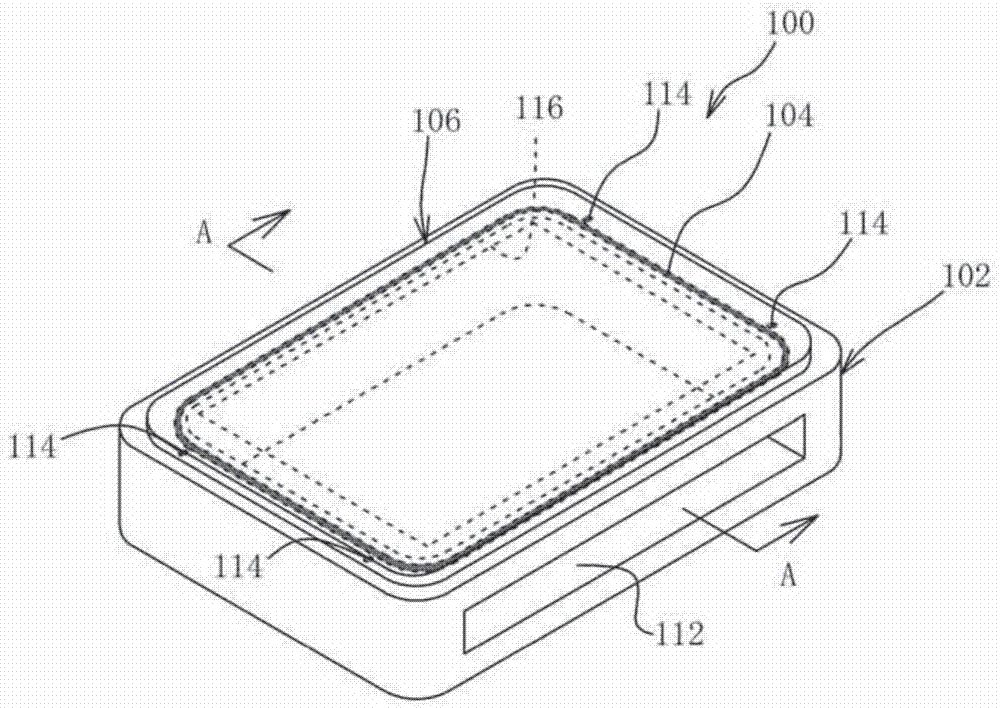
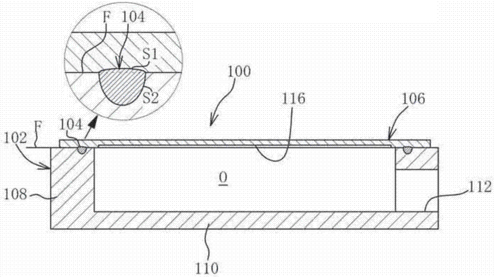
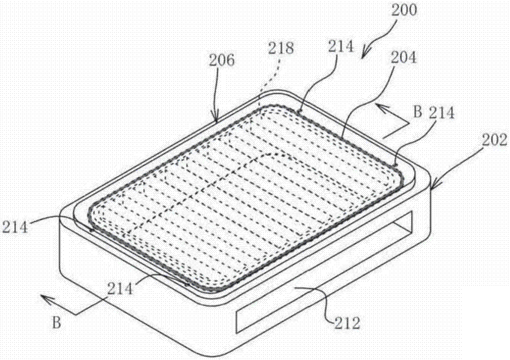
The invention provides a joint structure and a method of manufacturing the joint structure, and members connected with each other can be uniformly and assuredly sealed without using a glass plate. Thejoint structure comprises a light-absorbable member having at least one opening portion and a light-permeable member superposed on the light-absorbable member so as to cover the opening portion, wherein a first annular weld part is formed so as to enclose the opening portion and join the light-absorbable member and the light-permeable member, and a second dot-like weld part(s) joining the light-absorbable member and the light-permeable member is / are formed in a position adjacent to the first weld part.

Description

Technical field [0001] The present invention relates to a joined structure including a light-absorbing member and a light-transmitting member that overlap each other and are joined to each other via a welded portion formed in the boundary surface or the vicinity of the boundary surface, and a method of manufacturing the same. Background technique [0002] Previously, as a method of joining a plurality of members, there is a joining method using laser light irradiation. Among them, there has recently been attention to a laser transmission welding that performs local heating to reduce thermal damage to the product and has less influence on the appearance of the welded part. Method (Laser Transmission Welding). This bonding method is a method in which one of the bonding members uses a member that is transparent to laser light (light transmissive member), and the other uses a member that is absorbing to laser light (light absorbing member) In the state where these are superimposed a...

Claims


Application Information

Patent Timeline
Patent Type & Authority Applications(China)
IPC IPC(8): B29C65/16
CPCB29C65/1635B29C66/41B29C66/82B29C66/9241B29C66/929B23K26/206B23K26/244B29L2031/3481B29C66/114B29C66/21B29C65/1677B29C66/343B29C66/836B29C66/53461B29C65/7855B29C66/3452B29C66/1122B29C66/73921B29C65/1658B29C66/24244B29C66/82423B29C65/1616B29L2031/36B29C65/1619B29C66/112B29C66/71B29C65/1606B29C66/82661B29K2021/003F16B5/08
Inventor 山岸裕幸
Owner FUJIKURA LTD
Why Eureka
Try Eureka