Steam valve assembly and steam heating device

A steam heating device and steam valve technology, applied in the field of kitchen utensils, can solve the problems of reducing the reflux speed of viscous liquid and the difficulty of normal condensation of viscous liquid, and achieve the effects of fast reflux speed, large exhaust volume and high exhaust efficiency

Active Publication Date: 2018-04-06
GREE ELECTRIC APPLIANCES INC
View PDF5 Cites 8 Cited by
  • Summary
  • Abstract
  • Description
  • Claims
  • Application Information

AI Technical Summary

Problems solved by technology

[0004] The main defect of the existing steam valve is that the fan blades are arranged in the chamber, and the rotation of the fan blades keeps most of the liquid-laden steam in a state of motion in the chamber, which makes it difficult for the viscous liquid in the liquid-laden steam to condense normally, reducing the viscosity. liquid return velocity

Method used


Image

  • Steam valve assembly and steam heating device
  • Steam valve assembly and steam heating device
  • Steam valve assembly and steam heating device

Examples


Embodiment 1

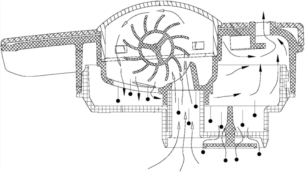
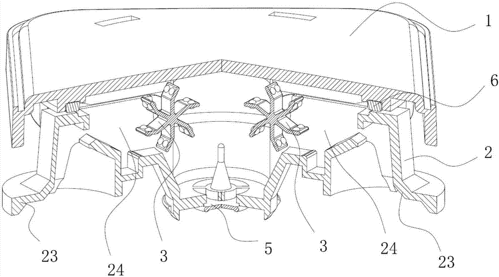
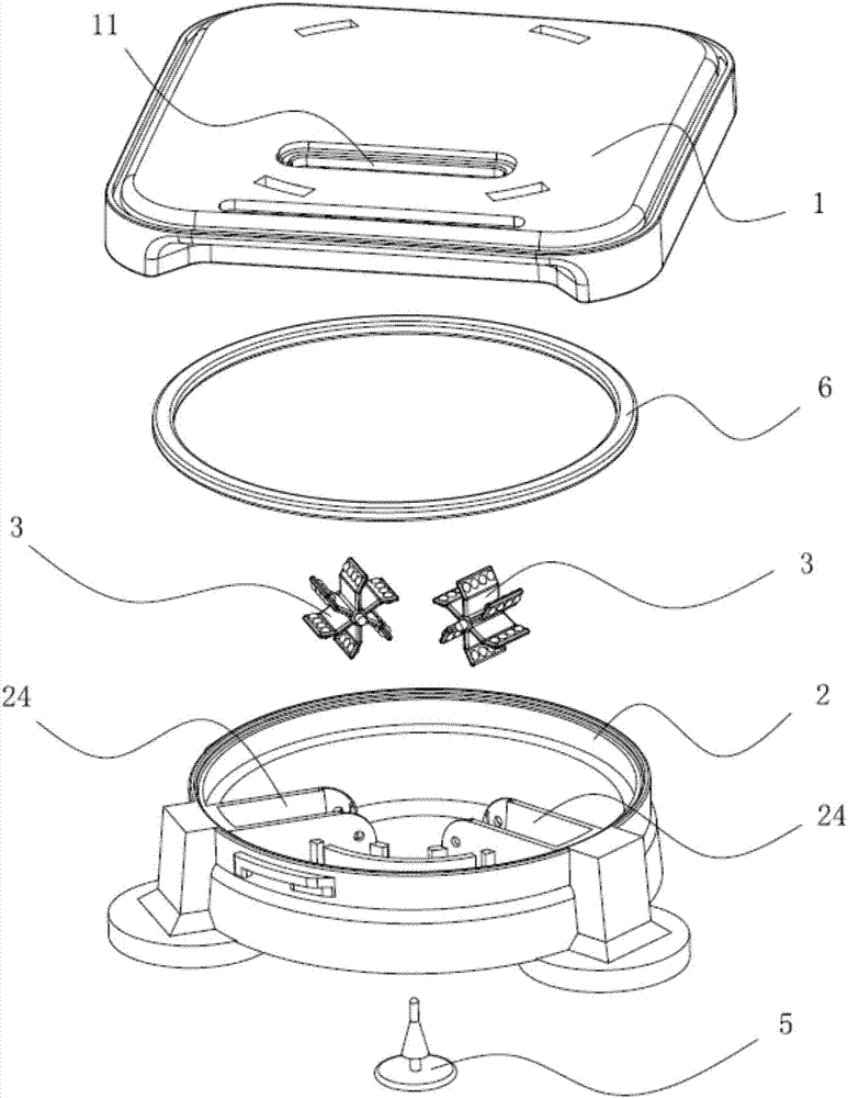
[0046] This embodiment discloses a steam valve assembly and a steam heating device including the steam valve assembly. Such as figure 2 and image 3 As shown, the steam valve assembly includes a valve cover 1, a valve seat 2 and a bubble-breaking fan blade 3. The valve cover 1 is provided with an air outlet 11, and the valve seat 2 is provided with an air inlet 23 communicating with the interior of the steam heating device. , the air outlet 11 and the air inlet 23 communicate with the steam chamber 4 respectively. A steam passage 24 is provided between the air inlet 23 and the steam chamber 4 , and the bubble-breaking fan blade 3 is arranged in the steam passage 24 . In order to prevent steam leakage from the periphery of the steam valve assembly, a sealing ring 6 is provided between the valve cover 1 and the valve seat 2 . After a certain amount of viscous liquid accumulates at the bottom of the steam chamber 4, it will press the return pad 5 to open it, and the viscous l...

Embodiment 2

[0064] This embodiment discloses a steam valve assembly and a steam heating device including the steam valve assembly, the structure of which is basically the same as that of Embodiment 1. The difference is that: if Figure 16 As shown, the bubble-breaking fan blade 3 is installed in the valve cover blade installation hole 13 on the valve cover 1. After the valve cover 1 and the valve seat 2 are installed, the bubble-breaking fan blade 3 is still located in the steam channel 24, and its function And the method of use is the same as in Example 1.

[0065] Such as Figure 17 and Figure 18 As shown, only one steam channel 24 is provided between the air inlet 23 and the steam chamber 4, the manufacturing cost is lower, and the flow of steam is easier to be effectively controlled.

[0066] The rotating shaft of the bubble-breaking fan blade 3 can also be vertically arranged between the valve cover 1 and the valve seat 2, so that the efficiency of crushing or squeezing the bubbl...


PUM


Abstract

The invention discloses a steam valve assembly and a steam heating device, belonging to the technical field of kitchen ware, and being designed aiming at solving the problem of the existing steam valve assembly that viscous liquid is hard to condense to reflow. The steam valve assembly comprises a valve cover, a valve seat and a bubble breaking fan blade, wherein an air outlet is formed in the valve cover, an air inlet communicated with the interior of the steam heating device is formed in the valve seat, the air outlet and the air inlet are respectively communicated with a steam chamber, a steam channel is arranged between the air inlet and the steam chamber, and the bubble breaking fan blade is arranged in the steam channel. The steam heating device comprises the steam valve assembly. According to the bubble breaking fan blade of the steam valve assembly and the steam heating device, formed bubbles in steam with liquid can be broken or crushed, the forming of new bubbles can be prevented, and the temperature of the steam with liquid can be reduced. Gas discharged from the air outlet is mostly common steam instead of steam with liquid, so that the problem that bubbles are formed at the air outlet is solved, the air exhaust temperature is low, the air discharge amount is great and the air discharge efficiency is high.

Description

technical field [0001] The invention relates to the technical field of kitchen utensils, in particular to a steam valve assembly and a steam heating device comprising the steam valve assembly. Background technique [0002] The working principle of the steam heating device is to use high-pressure steam to shorten the cooking time, and it is widely used in the field of kitchen utensils, such as pressure cookers. High-pressure steam has a lot of energy. If a certain amount of steam is not discharged in time during use, the container may explode. Therefore, the existing steam heating devices are equipped with steam valves of various structures. [0003] When the steam heating device is steaming rice porridge and other substances that will produce viscous liquid, the direct discharge of steam will cause part of the viscous liquid to overflow directly from the air outlet along with the steam, resulting in bubbling in the steam valve and affecting the normal discharge of steam. In...

Claims


Application Information

Patent Timeline
Patent Type & Authority Applications(China)
IPC IPC(8): A47J27/08A47J27/04A47J36/38
CPCA47J27/04A47J27/08A47J36/38A47J2027/043
Inventor 陈亮高塬贵陈冬冬李锦彬陈伟李振合成灿明胡玉新潘泽勇康津
Owner GREE ELECTRIC APPLIANCES INC
Why Eureka
Try Eureka