


Quick Research
Generate reliable direction feasibility study reports for your R&D in just a few steps.

Technical Q&A
Discover and master advanced knowledge NOW. Basics, ideas, possibilities, all at once.

Find Solutions
As an expert in R&D theories, this can generate solutions to your technical problems instantly.

Evaluate Feasibility
Analyze your overall solution with one click, know your potential R&D risks in advance.

Monitor Landscape
Get weekly tech updates, stay abreast of the latest tech innovations and key insights.
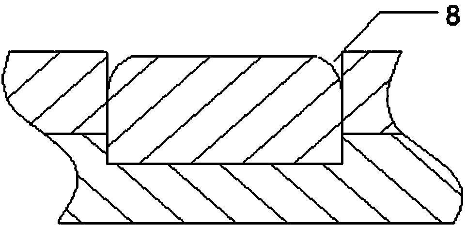
Method for eliminating keyhole-free friction stir spot welding ring groove
A friction stir and spot welding technology, used in welding equipment, non-electric welding equipment, welding/welding/cutting items, etc., it can solve problems such as the gap between the stirring sleeve and the pressing sleeve becoming larger, affecting the mechanical properties of the solder joints, and metal loss. , to achieve easy operation, solve welding ring groove defects, and achieve remarkable results
- Summary
- Abstract
- Description
- Claims
- Application Information
AI Technical Summary
Problems solved by technology
Method used
Image

Examples
Embodiment 1
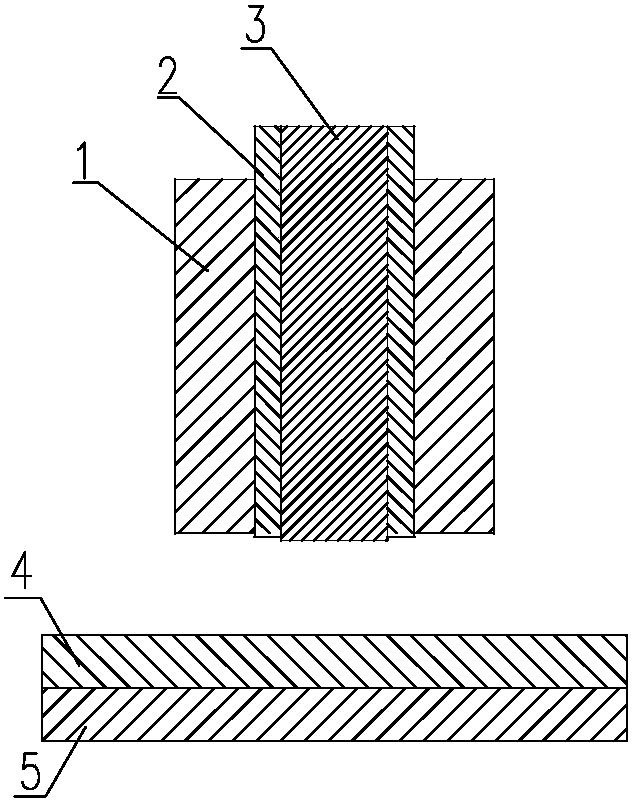
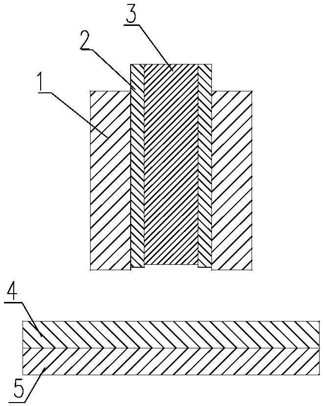
[0036] like Figure 2-7 The shown method for eliminating the ring groove of keyhole friction stir spot welding includes the following steps:
[0037] 1) Base material preparation: the base material thickness is 1 mm, which is two layers, namely the upper base material 4, the lower base material 5,
[0038] 2) Pre-welding preparation: install stirring tools on the welding equipment, wherein the stirring tools are respectively stirring needle 3, stirring sleeve 2 and compression sleeve 1 from the inside to the outside;
[0039] 3) Zero point setting: Before welding, take the bottom surface of the compression sleeve 1 as the reference plane, adjust the equipment so that the stirring needle 3 protrudes downward from the reference plane, and the length of the stirring needle 3 protruding from the reference plane is 0.1mm; at the same time, adjust the equipment so that The stirring sleeve 2 protrudes downwards from the reference plane, and the length of the stirring sleeve 2 protru...
Embodiment 2
[0048] like Figure 2-7 The shown method for eliminating the ring groove of keyhole friction stir spot welding includes the following steps:
[0049] 1) Base material preparation: the base material thickness is 3 mm, which is two layers, that is, the upper base material 4, the lower base material 5,
[0050] 2) Pre-welding preparation: install stirring tools on the welding equipment, wherein the stirring tools are respectively stirring needle 3, stirring sleeve 2 and compression sleeve 1 from the inside to the outside;
[0051] 3) Zero point setting: Before welding, take the bottom surface of the compression sleeve 1 as the reference plane, adjust the equipment so that the stirring needle 3 protrudes downward from the reference plane, and the length of the stirring needle 3 protruding from the reference plane is 0.2mm; at the same time, adjust The equipment makes the stirring sleeve 2 protrude downward from the reference plane, and the length of the stirring sleeve 2 protrudi...
Embodiment 3
[0060] like Figure 2-7 The shown method for eliminating the ring groove of keyhole friction stir spot welding includes the following steps:
[0061] 1) Base material preparation: the base material thickness is 5mm, which is two layers, namely the upper base material 4 and the lower base material 5,
[0062] 2) Pre-welding preparation: install stirring tools on the welding equipment, wherein the stirring tools are respectively stirring needle 3, stirring sleeve 2 and compression sleeve 1 from the inside to the outside;
[0063] 3) Zero point setting: Before welding, take the bottom surface of the compression sleeve 1 as the reference plane, adjust the equipment so that the stirring needle 3 protrudes downward from the reference plane, and the length of the stirring needle 3 protruding from the reference plane is 0.2mm; at the same time, adjust The equipment makes the stirring sleeve 2 protrude downward from the reference plane, and the length of the stirring sleeve 2 protrudi...
PUM
| Property | Measurement | Unit |
|---|---|---|
| length | aaaaa | aaaaa |
| length | aaaaa | aaaaa |
| thickness | aaaaa | aaaaa |
Abstract
Description
Claims
Application Information
 - R&D Engineer
- R&D Manager
- IP Professional
- Industry Leading Data Capabilities
- Powerful AI technology
- Patent DNA Extraction
Browse by: Latest US Patents, China's latest patents, Technical Efficacy Thesaurus, Application Domain, Technology Topic, Popular Technical Reports.
© 2024 PatSnap. All rights reserved.Legal|Privacy policy|Modern Slavery Act Transparency Statement|Sitemap|About US| Contact US: help@patsnap.com