
Cervical vertebra interbody fusion cage

A technology of intervertebral fusion and cervical spine, applied in the field of cervical intervertebral fusion, can solve problems such as close contact of hook vertebral joints, affecting the effect of bone graft fusion, and backward displacement of bone graft materials, so as to reduce surgical risks and enhance The effect of intervertebral fusion, the effect of improving the effect of intervertebral fusion

Pending Publication Date: 2018-03-30
WEST CHINA HOSPITAL SICHUAN UNIV
View PDF1 Cites 6 Cited by
  • Summary
  • Abstract
  • Description
  • Claims
  • Application Information

AI Technical Summary

Problems solved by technology

[0003] Patent document (CN203291002U) discloses a cervical vertebral hook joint fusion device, but the bone graft material of the fusion device cannot be in close contact with the hook vertebral joint, which is not conducive to bone graft fusion
In addition, the intervertebral fusion cage has the possibility of the bone graft material being displaced backward and entering the spinal canal, thus increasing the risk of surgery
[0004] Furthermore, the currently disclosed intervertebral fusion devices are all single bone grafts between the endplates or in the lateral area, and the contact between the bone graft material and the bone graft bed is less, which affects the fusion effect of the bone graft.

Method used


Image

  • Cervical vertebra interbody fusion cage
  • Cervical vertebra interbody fusion cage
  • Cervical vertebra interbody fusion cage

Examples


Embodiment 1

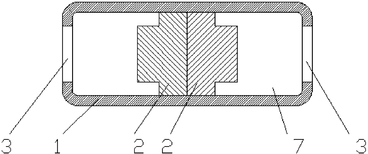
[0045] Such as figure 1 , 2 As shown in . Bone grafting window 3, bone grafting window 3 communicates with bone grafting cavity 7; stretching slider 2 is arranged in bone grafting cavity 7 and can slide in bone grafting cavity 7; support body 1 has a horizontally arranged The chute 4 communicates with the bone graft inner cavity 7 . Such as Figure 4 As shown, there is a straight arm 5 on the stretching slider 2, and the straight arm 5 protrudes from the chute 4, and there are external threads on the straight arm 5; there are two stretching sliders 2, and the support body 1 has a The fixation nails are nailed 6. According to different installation positions, the position and structure of the fixing nail channel 6 will be adaptively changed. Support body 1 adopts anatomical design, and its shape is compatible with the shape of the upper and lower endplates and the uncinate joint, and is in close contact with the endplate. The material of support body 1 is polyether ether k...

Embodiment 2

[0050] The difference between this embodiment and Embodiment 1 is that the two stretching sliders 3 can slide towards a bone graft window 3 in one direction respectively, specifically, the stretching slider 3 on the left side moves toward the bone grafting window 3 on the left. One-way sliding; the stretching slider 3 on the right slides one-way to the right bone graft window 3. There are many structures for realizing one-way sliding. For example, two groups of one-way teeth are arranged on the bottom surface of the bone graft inner cavity 7, and the two groups of one-way teeth face to the left and right sides respectively. elastic sheet. another example Figure 9 , 10As shown, there are two sets of inclined shrapnels 15 on the bottom surface of the bone graft inner cavity 7, one set of shrapnels 15 is inclined to the right, and the other set of shrapnels 15 is inclined to the left. When the stretching slider 3 is stretched, it can overwhelm the shrapnel 15 and slide toward...

Embodiment 3

[0052] The difference between this embodiment and embodiment 1 or 2 is: as Figure 11 , 12 , 13, the center of the support body 1 is vertically provided with a partition block 14, the partition block 14 divides the bone graft inner cavity 7 into left and right two independent chambers 71, and the two stretching sliders 2 are respectively arranged on the One of the chambers 71. A bone graft channel 10 is vertically arranged in the center of the partition block 14 , and the bone graft channel 10 runs through the top surface and the bottom surface of the support body 1 .

[0053] When used, such as Figure 14 , 15 As shown, bone grafting can be provided between the upper and lower endplates and the hook vertebral joints on both sides, so that the surrounding bone grafting can be performed in the surgical space, which increases the contact area between the bone grafting material and the bone grafting bed, and further strengthens the intervertebral joints. fusion effect.


PUM


Abstract

The invention relates to a cervical vertebra interbody fusion cage which comprises a supporting body and distraction sliders. A bone grafting inner cavity is formed in the supporting body. The left side and the right side of the supporting body are each provided with a bone grafting window which is communicated with the bone grafting inner cavity. The distraction sliders are arranged in the bone grafting inner cavity. The two distraction sliders can slide to the bone grafting windows in one direction respectively. Baffles are arranged behind the bone grafting windows. The end faces, facing thebone grafting windows, of the distraction sliders are provided with developing marks where X-rays can not permeate. By means of the distraction sliders in the fusion cage, a bone grafting material and uncovertebral joints can be closely combined, and the interbody fusion effect is effectively improved; a bone grafting channel which is vertically through is formed in the supporting body, bone grafting can be conducted between upper and lower end plates and the uncovertebral joints on the two sides, surrounding type bone grafting is conducted on a surgery break, the contact area of the bone grafting material and a bone grafting bed is increased, and the interbody fusion effect is further enhanced; the baffles are arranged behind the bone grafting windows, the bone grafting material can be prevented from entering vertebral canal, and surgical risks are reduced.

Description

technical field [0001] The invention relates to the technical field of medical instruments, in particular to a cervical intervertebral fusion device. Background technique [0002] Anterior cervical decompression and fusion (ACDF) is an important surgical procedure for the treatment of cervical spondylosis, and early and effective intervertebral fusion is an important factor affecting the clinical efficacy of ACDF. The commonly used intervertebral fusion device achieves intervertebral fusion through bone grafting between endplates, but clinical observations show that its early fusion rate is not optimistic. Due to the short distance between the upper and lower bone surfaces and rich blood supply in the lateral cervical spine and the uncinate joint area, clinical observations have shown that the healing effect of bone grafting in this area is better. Adequate contact and tight integration between the bone graft material and the bone graft bed are the basis for satisfactory bo...

Claims


Application Information

Patent Timeline
IPC IPC(8): A61F2/44
CPCA61F2/4455A61F2310/00005A61F2250/0098
Inventor 孟阳刘浩洪瑛王贝宇
Owner WEST CHINA HOSPITAL SICHUAN UNIV
Learn More