Culture room used for planting of Pleurotus eryngii
A technology for cultivating houses and Pleurotus eryngii, which is applied in plant cultivation, mushroom cultivation, cultivation, etc., and can solve the problems of heating motor damage, leakage, and short service life
- Summary
- Abstract
- Description
- Claims
- Application Information
AI Technical Summary
Problems solved by technology
Method used
Image
Examples
Embodiment 1
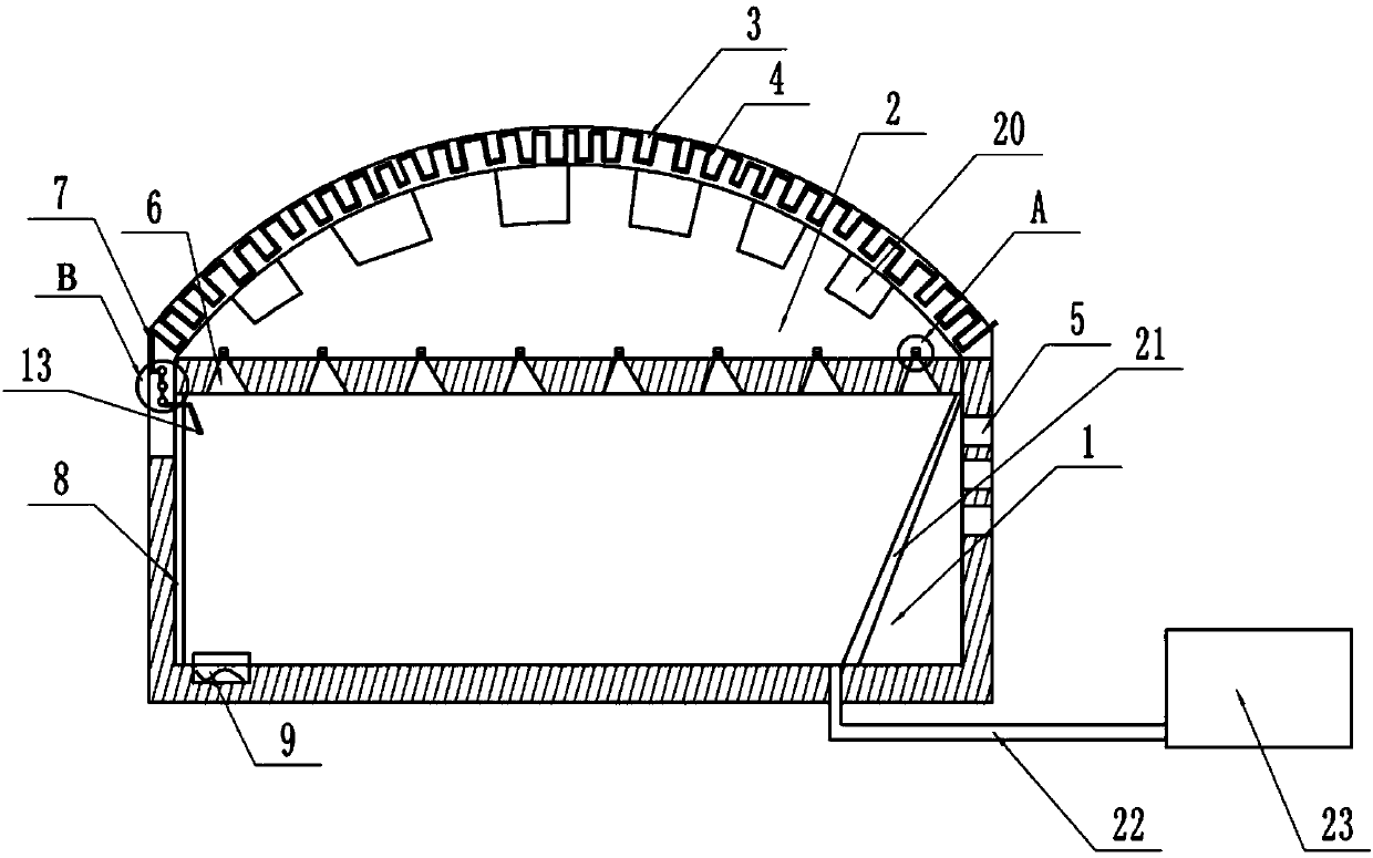
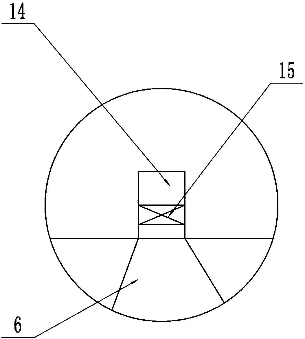
[0026] Basic as attached figure 1 Shown: a cultivation room for planting Pleurotus eryngii, including a steaming layer 1, a cultivation layer 2 and a drying layer 3, the drying layer 3 is arranged above the cultivation layer 2, and the cultivation layer 2 is arranged on the bottom of the steaming layer 1 Above, a steam device is provided at the bottom of the steam layer 1, and the steam device includes an induction cooker 9 and a steaming plate, the steaming plate is arranged above the induction cooker 9, and the top of the steam layer 1 is provided with a steam trap 6, such as figure 2 As shown, the cross section of the steam receiving tank 6 is an inverted triangle, and the notch of the steam receiving tank 6 is provided with a nozzle 14, and the nozzle 14 faces the storage tank 20 in the cultivation layer 2, so designed, the water in the steam layer 1 can be The steam is concentrated in the steam receiver 6, because the size of the inlet of the steam receiver 6 is greater ...
Embodiment 2
[0035] The difference from Example 1 is that, as Figure 4 As shown, the water volume control device includes a guide tube 7 and several soft balls 10, two adjacent soft balls 10 communicate with each other, the soft ball 10 located at the lower part of the water volume control device is connected to the nozzle 12, and the soft ball located at the upper part of the water volume control device 10 is connected with guide pipe 7, is provided with valve in guide pipe 7, is positioned at the soft ball 10 of water control device bottom and connects nozzle 12, is provided with second valve in nozzle 12. Start the valve, when the water flows into the soft ball 10 through the guide pipe 7, and when the entire water control device is filled, close the second valve, and the second valve divides the water into two ends, one section is located at the position of the soft ball 10, and the other section is located at the nozzle pipe 12, and the mouth of the spray pipe 12 faces the steaming t...
Embodiment 3
[0037] The difference from Example 1 is that, as Figure 5 As shown, the water volume control device includes a guide tube 7, several soft balls 10, a collection ball 16 and a folded tube 17, the soft ball 10 and the collection ball 16 are connected by a folded tube 17, and the soft ball 10 on the top of the water volume control device and the guide tube 7 is connected, and the guide pipe 7 is provided with a valve, and the soft ball 10 positioned at the bottom of the water control device is connected to the nozzle 12, and the nozzle 12 is provided with a third valve. Start the valve, when the water flows into the soft ball 10 through the guide tube 7, the water flow velocity will first fill part of the area of the soft ball 10, and at the same time flow into the collection ball 16 through the folded tube 17, and then flow into the second soft ball 10 through the folded tube 17. In the ball 10, when the water is full of the entire water control device, the third valve is clo...
PUM
 Abstract
Description
Claims
Application Information
 - Generate Ideas
- Intellectual Property
- Life Sciences
- Materials
- Tech Scout
- Unparalleled Data Quality
- Higher Quality Content
- 60% Fewer Hallucinations
Browse by: Latest US Patents, China's latest patents, Technical Efficacy Thesaurus, Application Domain, Technology Topic, Popular Technical Reports.
© 2025 PatSnap. All rights reserved.Legal|Privacy policy|Modern Slavery Act Transparency Statement|Sitemap|About US| Contact US: help@patsnap.com


