
Moisture flow measurement device based on exempt-level radioactive source

A flow measurement device and technology of the measurement device, applied in the direction of mass flow measurement device, indirect mass flowmeter, etc., can solve the problems of decreased measurement accuracy, difficult industrial use, difficult accurate detection, etc., and achieve low noise amplitude, convenient manufacturing, and reduced The effect of air-liquid slip

Pending Publication Date: 2018-03-27
WUXI SEA PIONEERS TECH CO LTD
View PDF0 Cites 2 Cited by
  • Summary
  • Abstract
  • Description
  • Claims
  • Application Information

AI Technical Summary

Problems solved by technology

However, because of the very low activity of exempted radioactive sources, for industrial large-caliber wet gas pipelines, the gamma rays emitted by exempted radioactive sources are often very weak and difficult to detect accurately after passing through the venturi throat, resulting in measurement Accuracy drops
This makes it almost impossible to use industrially

Method used


Image

  • Moisture flow measurement device based on exempt-level radioactive source
  • Moisture flow measurement device based on exempt-level radioactive source
  • Moisture flow measurement device based on exempt-level radioactive source

Examples


Embodiment 1

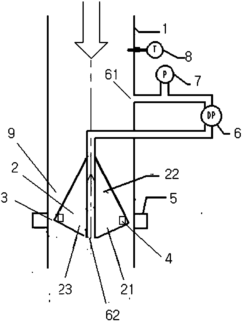
[0034] Such as figure 1 As shown, the wet gas flow measurement device based on the exempt radioactive source of the present invention includes a section of cylindrical pipe 1 and a conical throttling member 2 located in it and coaxially arranged therewith, and the conical throttling member 2 includes a common The head cone section 22 and the tail cone section 23 arranged on the bottom surface have the same bottom area, wherein the head cone section 22 faces the moisture inlet of the cylindrical pipe 1, and the maximum diameter of the conical throttling member 2 is An annulus 3 is defined between the place 21 and the inner wall of the cylindrical pipe 1 for the passage of moisture; at the place 21 of the largest diameter of the conical throttling member 2, an exemption level radioactive source Ba is arranged 133 The material block 4 whose activity is lower than 25 μCi is arranged in such a way that the gamma rays emitted by it can penetrate the annulus 3 in the radial direction...

Embodiment 2

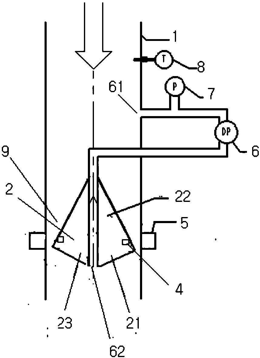
[0062] structured as figure 2 shown, which is the same as figure 1 The difference in the structure shown is that the position of the exempt level radioactive source is on the conical surface of the head cone section 22 of the conical throttling member 2, and its position is close to the maximum diameter 21 of the conical throttling member 2, which is arranged The gamma rays emitted by the gamma rays can radially penetrate the tapered annulus space 9) and reach the gamma ray detector 5 located outside the cylindrical pipe 1, wherein all the gamma rays at the places where the gamma rays pass through The radial width of the tapered annular space 9 is less than 50 mm.

[0063] The specific mass flow calculation method is exactly the same as that in Embodiment 1.


PUM

PropertyMeasurementUnit
Cone angleaaaaaaaaaa

Abstract

The invention discloses a moisture flow measurement device based on an exempt-level radioactive source. The moisture flow measurement device is characterized in that the device comprises a section ofcylindrical pipeline (1) and a tapered throttling part (2) which is located in the section of cylindrical pipeline and arranged in the same axis as the section of cylindrical pipeline; the tapered throttling part (2) comprises a head conical section (22) and a tail conical section (23), both of which are arranged by sharing the same bottom surface; the head conical section (22) faces a moisture inlet of the cylindrical pipeline (1); an annular gap (3) is defined between the inner wall of the cylindrical pipeline (1) and a position with the largest diameter of the tapered throttling part (2) toallow moisture to pass through; the position with the largest diameter of the tapered throttling part (2) is equipped with exempt-level radioactive modules (4) which are arranged to enable emitted gamma rays to penetrate through the annular gap (3) along a radial direction; and therefore, the emitted gamma rays can reach gamma ray detectors (5) outside the cylindrical pipeline (1). The moisture flow measurement device based on the exempt-level radioactive source adopts the exempt-level radioactive source and is a major breakthrough in the field of multi-phase flow measurement equipment.

Description

technical field [0001] The invention belongs to the field of flow metering equipment, and in particular relates to a moisture flow metering device based on an exempt radioactive source. Background technique [0002] In the oil and gas industry, oil and gas well products contain both liquid-phase crude oil and gas-phase natural gas in a gas-liquid mixed fluid, which is called multiphase flow in the industry. Wherein said gas phase includes such as oil and gas field gas or any non-condensable gas at normal temperature, specifically as methane, ethane, propane, butane, etc.; said liquid phase may include: oil phase, such as crude oil itself and in the crude oil extraction process Liquid additives dissolved in crude oil, and aqueous phases, such as formation water, water injected into oil and gas wells during production, and other liquid additives dissolved in the aqueous phase. In practice, the oil and water phases may be phase separated, mixed together, or completely emulsifi...

Claims


Application Information

Patent Timeline
IPC IPC(8): G01F1/86G01F1/88
CPCG01F1/86G01F1/88
Inventor 徐斌陈继革郭朋李敬阳
Owner WUXI SEA PIONEERS TECH CO LTD
Learn More