
Gear rack drilling machine lifting device

A technology of rack and pinion, drilling rig, applied in the direction of support device, drill pipe, drill pipe, etc., can solve the problems of meshing and dislocation of the rack and pinion, achieve the effect of good meshing, large load and thrust, and reduce drilling cost

Pending Publication Date: 2018-03-27
SINOPEC OILFIELD EQUIP CORP +1
View PDF0 Cites 3 Cited by
  • Summary
  • Abstract
  • Description
  • Claims
  • Application Information

AI Technical Summary

Problems solved by technology

[0003] The purpose of the present invention is to provide a simple structure, easy to use, to solve the problem of misalignment of the rack and pinion caused by the offset and rack deflection of the existing lifting device in the loaded state, and can provide greater load and stop. The rack and pinion drilling rig lifting device that guarantees the self-safety strength of the rack and pinion mechanism at the same time

Method used


Image

  • Gear rack drilling machine lifting device
  • Gear rack drilling machine lifting device
  • Gear rack drilling machine lifting device

Examples


Embodiment Construction

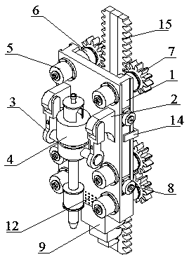
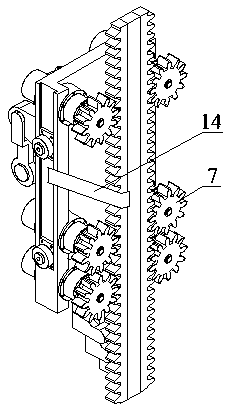
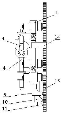
[0021] The rack and pinion drilling rig lifting device is composed of a mounting plate 1, a driver 4, a hydraulic motor 5, a reducer 6, a gear 7 and a straightener. There are multiple groups of hydraulic motors 5 and reducers 6 fixedly installed, gears 7 are installed on the reducers 6 through splines, drivers 4 are installed on the mounting plate 1 between the hydraulic motors 5 through symmetrically arranged fixed ears 2 and lifting rings 3 The guide rollers 8 are installed symmetrically on both sides of the mounting plate 1, and slide on the guide rail of the derrick through the guide rollers 8 to limit the operation of the lifting device, thereby ensuring that the lifting device will not deviate from the working space. 7-shaped hoops 14 are symmetrically arranged on the mounting plate 1 between the guide rollers 8 . The hoop 14 is slidably connected with the rack 15 on the derrick.

[0022] The lower end of the mounting plate 1 is equipped with a straightener through bolt...


PUM


Abstract

The invention relates to a gear rack drilling machine lifting device, and belongs to the technical field of mining and drilling tools for petroleum and nature gas. The gear rack drilling machine lifting device is composed of a mounting plate, driving machines, hydraulic motors, a retarder, gears and an alignment machine; multiple groups of hydraulic motors and retarders in a symmetric state are fixedly arranged at the two sides of the mounting plate through bolts, the retarders are provided with gears by splines; and the driving machines are arranged at fixed lugs and lifting rings symmetrically arranged at the mounting plate between the hydraulic motors, end surfaces of two sides of the mounting plate are symmetrically provided with guidance rollers, and the alignment machine is arrangedat the lower end of the mounting plate through bolts. According to the gear rack drilling machine lifting device, the problem of meshing and dislocating of gear racks caused by the deflection of an existing lifting device can be solved, right meshing of the gear racks is guaranteed to run the lifting device smoothly, the drilling efficiency is improved, the drilling cost is lowered, the security strength of the lifting device is guaranteed simultaneously, and further greater load and anti-thrust force can be provided.

Description

technical field [0001] The invention relates to a lifting device for a rack and pinion drilling rig, which belongs to the technical field of drilling tools for oil and natural gas exploitation. Background technique [0002] The oil drilling rig is a device used for oil drilling and drilling operations. The drilling rig mainly has two functions of lifting and rotating. The lifting function of the new rack and pinion drilling rig developed at home and abroad is mainly through the gear on the lifting device meshing with the rack installed on the derrick. To be done. However, the center of gravity of the hoisting device on the existing rack-and-pinion drilling rig is not in the same plane as the rack. When the hoisting device is working under load, due to eccentricity, the hoisting device will tilt forward, resulting in deflection when the gear and the rack mesh. Bending on one side is not conducive to the meshing of the rack-and-pinion mechanism, nor can it guarantee the safet...

Claims


Application Information

Patent Timeline
Patent Type & Authority Applications(China)
IPC IPC(8): E21B15/00E21B19/083
CPCE21B15/00E21B19/083
Inventor 冯定亢博文陈新龙施雷彭太锋李光金
Owner SINOPEC OILFIELD EQUIP CORP
Learn More