An evaporation source device for oled evaporation
An evaporation source and evaporation material technology, applied in vacuum evaporation plating, sputtering plating, ion implantation plating, etc., can solve the problems of decomposition or deterioration of organic materials, uneven distribution of organic materials, exposed bottom, etc., to reduce The effect of decomposing or deteriorating, reducing uneven heating, and avoiding partial exposure
- Summary
- Abstract
- Description
- Claims
- Application Information
AI Technical Summary
Problems solved by technology
Method used
Image
Examples
Embodiment 1
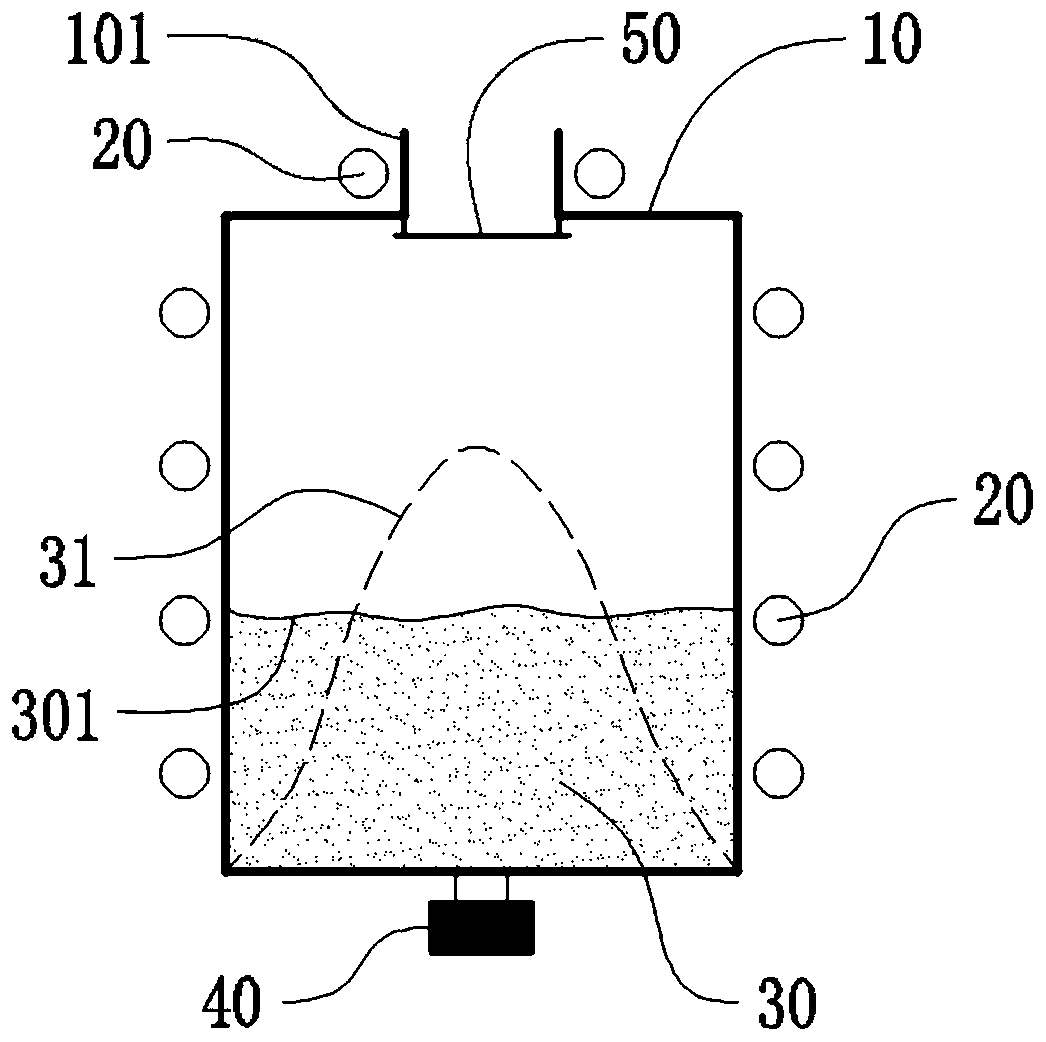
[0039] Such as figure 2 As shown, the present embodiment provides an evaporation source device for OLED evaporation, including an evaporation source body composed of a crucible 10 and a heater 20, the crucible 10 is heated by the heater 20, and an evaporation source body arranged on the evaporation source body The vibrator 40 on the evaporation source body can continuously or intermittently vibrate the vapor deposition material 30 in the crucible 10, so that the vapor deposition material 30 in the crucible 10 30 maintains the largest contact area with the side wall of the crucible 10 to improve the uniformity of heating of the evaporated material.
[0040] A heater 20 is also arranged around the nozzle 101 of the crucible 10 , and the heater 20 may be a resistance wire winding structure, so that the evaporation gas can be ejected smoothly when passing through the nozzle 101 without clogging the nozzle 101 . The crucible 10 is provided with a baffle 50 that can pass through t...
Embodiment 2
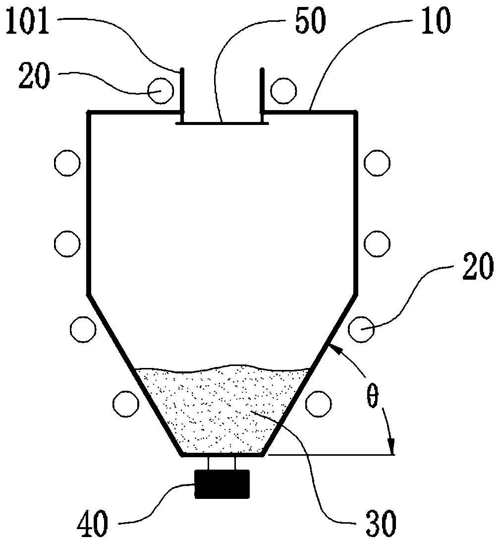
[0045] Such as image 3 As shown, this embodiment provides an evaporation source device for OLED evaporation, which has a structure similar to that of Embodiment 1, and the similarities will not be repeated. The difference between it and Embodiment 1 is that the lower part of the crucible 10 The structure is set as a trapezoidal cross-sectional shape with a large top and a small bottom, and a heater 20 is arranged around the trapezoidal inclined outer wall. By changing the structural shape of the crucible 10, the contact area between the vapor deposition material 30 and the side wall of the crucible is kept relatively large, which can avoid partial exposure of the bottom during the vapor deposition process. When the vapor deposition material 30 in the crucible is less, the evaporation can be reduced. Occurrence of local uneven heating of the material 30 can improve the uniformity of evaporation of the evaporation material 30 .
[0046] As a preferred solution of an evaporatio...
Embodiment 3
[0050] Such as Figure 5a , Figure 5b and Figure 6 As shown, this embodiment provides an evaporation source device for OLED evaporation, which has a structure similar to that of Embodiment 2, and the similarities will not be repeated. The difference between it and Embodiment 2 is that the crucible 10 With multi-point nozzles or linear nozzles, the crucible body is a combined structure of a hollow cuboid and a hollow quadrangular prism, which has all the advantages of Embodiment 1 and Embodiment 2.
[0051] Furthermore, in some optional implementations, the hollow quadrangular truss that makes up the crucible 10 can be inclined at 30° to 60° on all four sides (such as Figure 5a shown), or only two sides can be inclined at 30°~60° (such as Figure 5b shown), and Figure 5b The two inclined side surfaces in the center correspond to the direction in which the nozzles 101 are arranged.
[0052] Preferably, the vibrator 40 is arranged directly below the crucible 10, and more...
PUM
 Abstract
Description
Claims
Application Information
 - R&D Engineer
- R&D Manager
- IP Professional
- Industry Leading Data Capabilities
- Powerful AI technology
- Patent DNA Extraction
Browse by: Latest US Patents, China's latest patents, Technical Efficacy Thesaurus, Application Domain, Technology Topic, Popular Technical Reports.
© 2024 PatSnap. All rights reserved.Legal|Privacy policy|Modern Slavery Act Transparency Statement|Sitemap|About US| Contact US: help@patsnap.com


