
Automatic press-assembling machine for roller and bottom valve

A press-fitting machine and bottom valve technology, applied in metal processing, metal processing equipment, manufacturing tools, etc., can solve problems such as inaccurate assembly positions, affecting product stability, and high labor intensity, achieving simple structure, saving labor costs, The effect of high degree of automation

Inactive Publication Date: 2018-03-20
DONGGUAN UNIV OF TECH
View PDF0 Cites 0 Cited by
  • Summary
  • Abstract
  • Description
  • Claims
  • Application Information

AI Technical Summary

Problems solved by technology

[0002] The bottom valve is a kind of energy-saving valve, which is generally installed at the bottom of the suction pipe of the water pump to limit the return of the liquid in the pump pipe to the water source, and has the function of only entering and exiting. The function of support is flange connection and thread connection. The bottom valve is usually connected with pipeline components such as rollers. The traditional assembly process is usually manual assembly, which is time-consuming and labor-intensive, and the labor cost is high, and manual operation is easy to cause assembly position. Inaccurate, which affects the stability of the product, resulting in a high scrap rate. When the roller bottom valve is assembled in batches, it is labor-intensive and inefficient for the operator. This requires the design of an automatic roller bottom valve press. Machine

Method used


Image

  • Automatic press-assembling machine for roller and bottom valve
  • Automatic press-assembling machine for roller and bottom valve
  • Automatic press-assembling machine for roller and bottom valve

Examples


Embodiment Construction

[0039] In order to enable those skilled in the art to better understand the technical solution of the present invention, the present invention will be described in detail below in conjunction with the accompanying drawings. The description in this part is only exemplary and explanatory, and should not have any limiting effect on the protection scope of the present invention. .

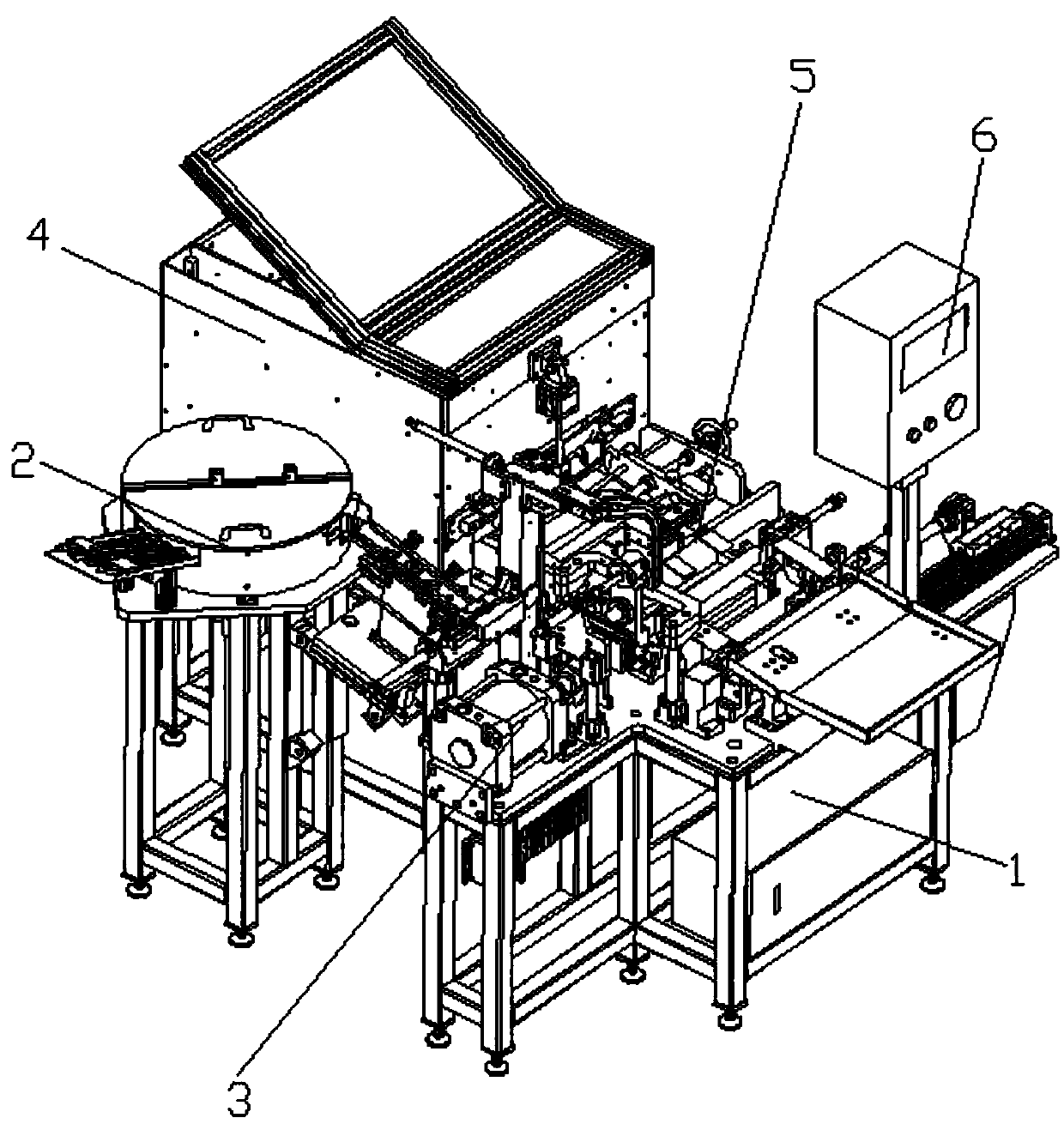
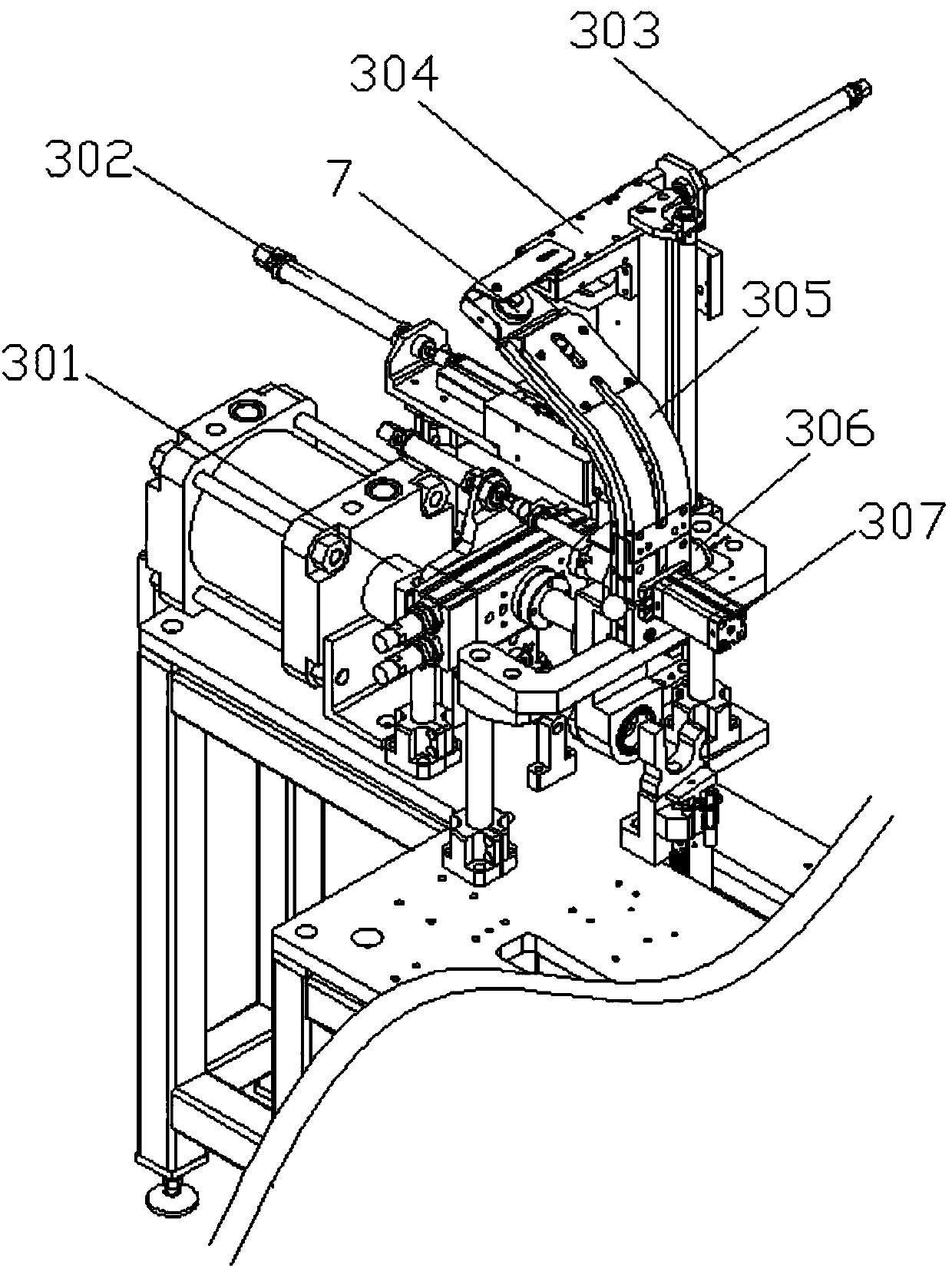
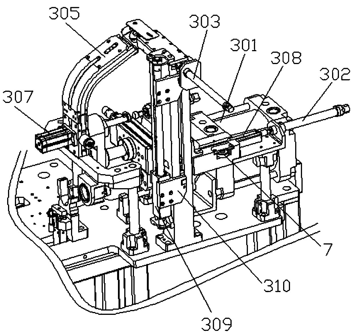
[0040] Such as Figure 1-Figure 13 Shown, the structure of the present invention is: a roller bottom valve automatic press-fitting machine, which includes a frame and a power distribution control box arranged in the frame, the frame is provided with a bottom valve conveying device and a man-machine interface, The starting end of the bottom valve conveying device is connected to the bottom valve feeding device, and the discharge end is connected to the pressing device, and the side of the pressing device is connected to the roller feeding device, and the bottom valve conveying device includes The botto...


PUM


Abstract

The invention relates to a roller bottom valve automatic press-fitting machine, which includes a frame and a power distribution control box arranged in the frame, a bottom valve conveying device and a man-machine interface are arranged on the frame, the starting end of the bottom valve conveying Valve feeding device, the discharge end is connected to the press-fitting device, the side of the press-fitting device is connected to the roller feeding device, the bottom valve conveying device includes a bottom valve pushing block, one end of the bottom valve pushing block is connected to the bottom valve pushing cylinder one, and the other end is matched with the bottom valve. The valve rises and pushes the block, and the bottom valve rises and pushes the block to connect the bottom valve rises the cylinder, and the bottom valve rises the cylinder to be installed on the bottom valve pushing slideway; the present invention provides the bottom valve through the bottom valve feeding device, and realizes the conveyance of the bottom valve through the bottom valve conveying device And steering, the roller is provided by the roller feeding device, the preliminary assembly of the bottom valve and the roller is realized under the action of the ejector mechanism, and the further assembly and unloading of the bottom valve and the roller are completed under the action of the pressing device, with a high degree of automation. The processing efficiency is greatly improved and the labor cost is saved.

Description

technical field [0001] The invention relates to the field of mechanical equipment, in particular to an automatic press-fitting machine for a roller bottom valve. Background technique [0002] The bottom valve is a kind of energy-saving valve, which is generally installed at the bottom of the suction pipe of the water pump to limit the return of the liquid in the pump pipe to the water source, and has the function of only entering and exiting. The function of support is flange connection and thread connection. The bottom valve is usually connected with pipeline components such as rollers. The traditional assembly process is usually manual assembly, which is time-consuming and labor-intensive, and the labor cost is high, and manual operation is easy to cause assembly position. Inaccurate, which affects the stability of the product, resulting in a high scrap rate. When the roller bottom valve is assembled in batches, it is labor-intensive and inefficient for the operator. This ...

Claims


Application Information

Patent Timeline
Patent Type & Authority Applications(China)
IPC IPC(8): B23P19/027B23P19/00
CPCB23P19/027B23P19/001
Inventor 钟守炎邓君
Owner DONGGUAN UNIV OF TECH
Learn More