
Urea pyrolysis denitrification control system

A control system and denitrification technology, applied in the field of urea pyrolysis denitration control system, can solve the problems of large hysteresis of control loop and poor anti-interference ability, etc.

Active Publication Date: 2018-03-20
YANTAI LONGYUAN POWER TECH +1
View PDF12 Cites 1 Cited by
  • Summary
  • Abstract
  • Description
  • Claims
  • Application Information

AI Technical Summary

Problems solved by technology

[0004] The embodiment of the present invention provides a urea pyrolysis denitrification control system, which solves the problems of large control loop hysteresis and poor anti-interference ability of the existing urea pyrolysis denitrification control system

Method used


Image

  • Urea pyrolysis denitrification control system
  • Urea pyrolysis denitrification control system

Examples


Embodiment 1

[0028] The first embodiment provides a urea pyrolysis denitration control system. The urea pyrolysis denitration control system includes: a denitration system and a predictive control system;

[0029] The predictive control system is used to obtain the controlled variable of the denitrification system, perform predictive control according to the controlled variable, and output to the denitrification system the total flow control command of urea generated according to the predictive control result;

[0030] The denitration system is used to control the total flow of the urea solution entering the pyrolysis furnace according to the total flow control command of urea, so that the absolute value of the difference between the NOx concentration at the outlet of the denitration system and the first set NOx concentration is less than or equal to the first preset value, Among them, the denitration system includes a pyrolysis furnace.

[0031] Urea pyrolysis ammonia production technology uses ...

Embodiment 2

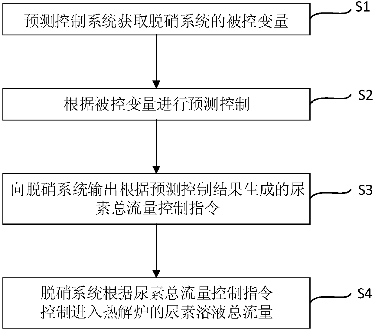
[0064] This embodiment provides a predictive control method for the urea pyrolysis denitrification control system, which is based on the urea pyrolysis denitrification control system in the first embodiment. figure 2 For the flow chart of the predictive control method of the urea pyrolysis denitrification control system, refer to figure 2 , The predictive control method includes the following steps:

[0065] S1: The predictive control system obtains the controlled variable of the denitration system;

[0066] S2: Predictive control based on the controlled variable;

[0067] S3: output to the denitration system the total flow control command of urea generated according to the predictive control result;

[0068] S4: The denitration system controls the total flow of the urea solution entering the pyrolysis furnace according to the total flow control command of urea.

[0069] Specifically, the predictive control module receives the controlled variable data from the controlled variable ad...


PUM


Abstract

The embodiment of the present invention discloses a urea pyrolysis denitrification control system. The urea pyrolysis denitration control system includes a denitration system and a predictive controlsystem; the predictive control system is used to obtain the controlled variable of the denitration system, performs predictive control according to the controlled variable, and outputs a urea total flow control command generated based on a predicted control result to the denitration system; the denitration system is used to control the total flow of a urea solution entering a pyrolysis furnace according to the urea total flow control command, so that absolute value of difference between the NOx concentration of the outlet of the denitration system and first preset NOx concentration is less than or equal to a first preset value. The total flow of the urea solution is taken as a control amount, and the total flow of the urea solution is given by the predictive control to realize the optimalcontrol of ammonia injection, the large lag of a control loop in the prior art can be overcome, the stability of the control system is improved, and the urea pyrolysis denitrification control system has the advantages of good stability, strong anti-interference ability and quick response, and the like.

Description

Technical field [0001] The embodiment of the present invention relates to the field of flue gas denitration, in particular to a urea pyrolysis denitration control system. Background technique [0002] Selective Catalytic Reduction (SCR) is currently the mainstream technology for denitration of tail gas in thermal power plants. Its principle is that ammonia gas is sprayed into the flue as a reducing agent, and under the action of a catalyst, nitrogen oxides in the flue gas are reduced to nitrogen and nitrogen. water. The preparation methods of ammonia mainly include the evaporation of liquid ammonia into ammonia, the pyrolysis of urea to prepare ammonia, and the hydrolysis of urea to prepare ammonia. Due to the high risk of liquid ammonia transportation and storage, many power plants have gradually changed to urea pyrolysis to prepare ammonia. gas. [0003] The existing urea pyrolysis denitrification control system has two control modes: a fixed molar ratio control mode and a prop...

Claims


Application Information

Patent Timeline
IPC IPC(8): B01D53/90B01D53/56G05B11/42
CPCB01D53/8625B01D53/8696B01D53/90B01D2251/2067B01D2258/0283G05B11/42
Inventor 隋海涛郝玉春刘晓哲任旻董璐赵超李修生崔强
Owner YANTAI LONGYUAN POWER TECH
Learn More