
High-efficiency environmentally-friendly dust-removing equipment

A kind of dust removal equipment and environmental protection technology, applied in the directions of dispersed particle separation, chemical instruments and methods, combined devices, etc., can solve the problems of exhaust gas emission not meeting the national emission standard, harassment of residents, difficult to disassemble, etc., to ensure the use effect and use. Benefit, enhance the function of use, the effect of high practicability

Inactive Publication Date: 2018-03-20
成都千里之行科技有限公司
View PDF0 Cites 3 Cited by
  • Summary
  • Abstract
  • Description
  • Claims
  • Application Information

AI Technical Summary

Problems solved by technology

However, due to the expansion of the production capacity of the enterprise, the emission of exhaust gas has also increased accordingly, and the original exhaust gas treatment equipment is stretched. In addition, the environmental protection companies are mixed, and there are some problems in the production equipment itself, which leads to the exhaust emission of the enterprise not reaching the national level. Emission standards, and even the exhaust gas treatment equipment of many companies have become decorations
As a result, the residents around the factory are harassed again, and some residents even suffer from severe respiratory diseases due to long-term exposure to this air, so they need to be equipped with dust removal equipment. However, the existing dust removal equipment has a complex structure and is not easy to disassemble. After that, the dust removal effect decreases

Method used


Image

  • High-efficiency environmentally-friendly dust-removing equipment
  • High-efficiency environmentally-friendly dust-removing equipment
  • High-efficiency environmentally-friendly dust-removing equipment

Examples


Embodiment Construction

[0016] The following will clearly and completely describe the technical solutions in the embodiments of the present invention with reference to the accompanying drawings in the embodiments of the present invention. Obviously, the described embodiments are only some, not all, embodiments of the present invention. Based on the embodiments of the present invention, all other embodiments obtained by persons of ordinary skill in the art without making creative efforts belong to the protection scope of the present invention.

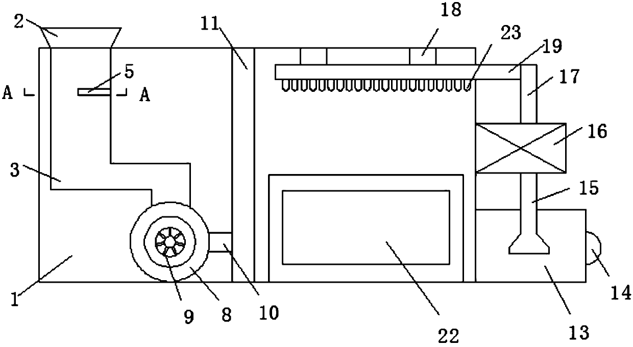
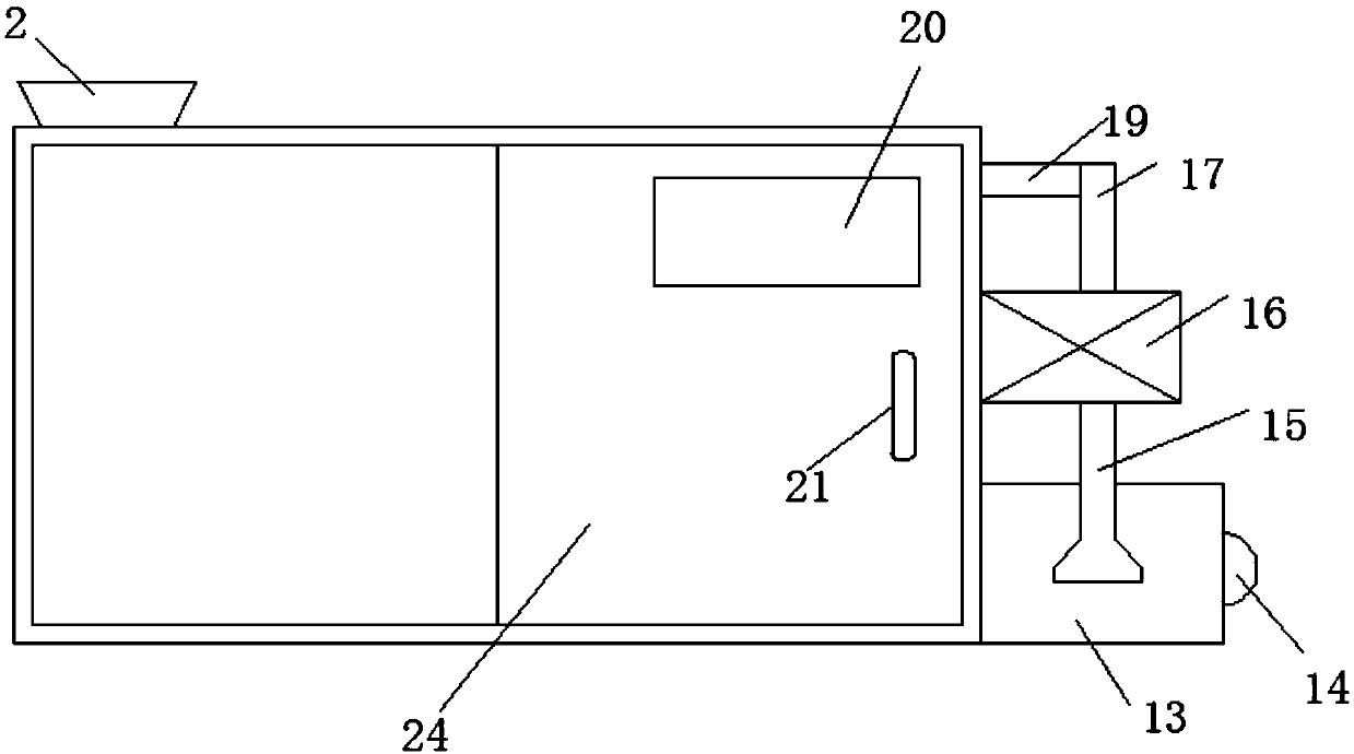
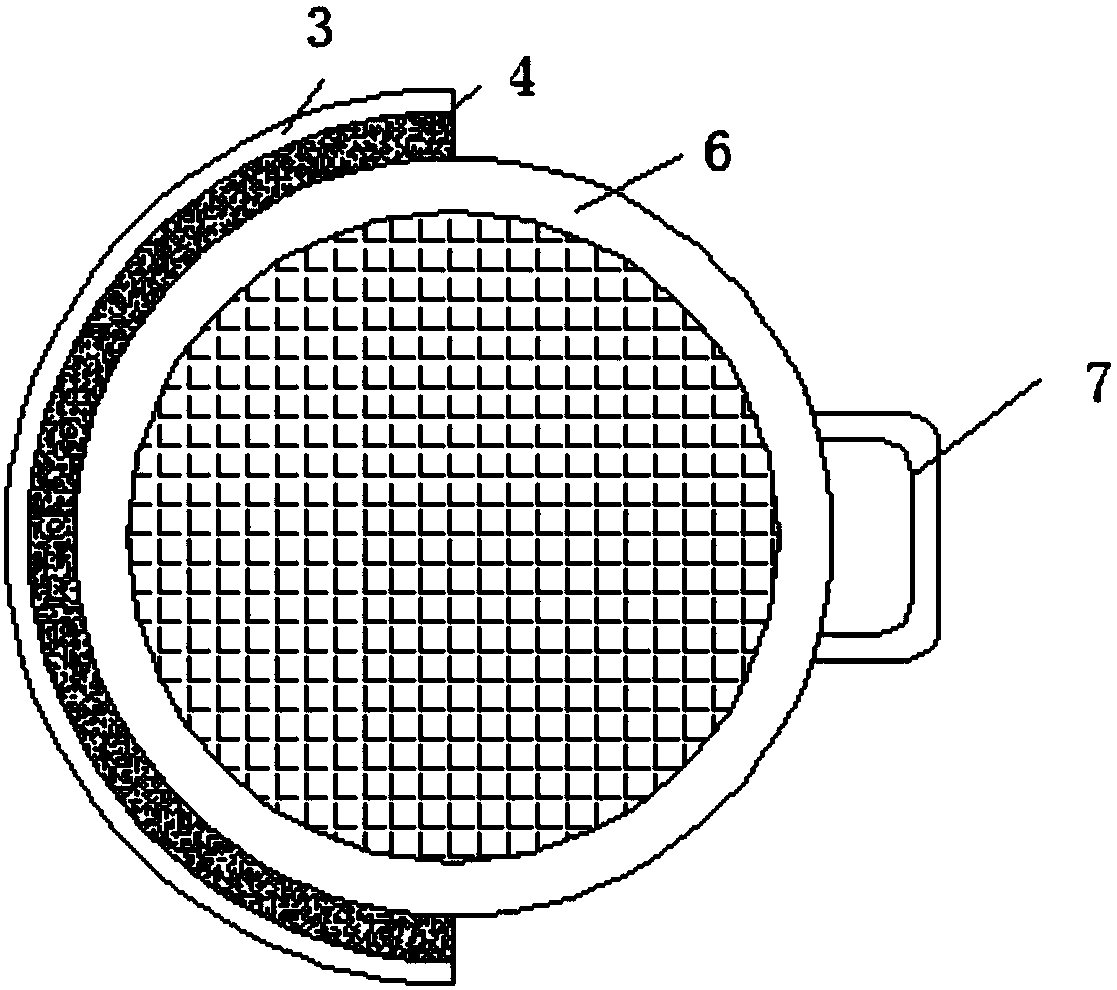
[0017] see Figure 1-4 , the present invention provides a technical solution: a high-efficiency environmental protection dust removal equipment, including a housing 1, a dust collection nozzle 2 is provided on the left side of the top of the housing 1, and a dust collection chamber is provided at the bottom of the dust collection nozzle 2 3. The right side of the upper half of the dust collection chamber 3 is connected with a filter screen 6 through the openin...


PUM


Abstract

The invention discloses high-efficiency environmentally-friendly dust-removing equipment. The equipment comprises a shell; a dust collecting mouth is arranged at the left side of the top of the shell,a dust collecting cavity is arranged at the bottom of the dust collecting mouth, and the right side of the upper half part of the dust collecting cavity is connected with a filter net through an opening groove. According to the invention, through the arrangement of the dust collecting mouth, the equipment is convenient for collecting dust into the interior of the dust collecting cavity; through the arrangement of the filter net, the equipment is convenient for filtering out some large particles firstly, and the large particles are left on the filter net; through the arrangement of the openinggroove, the equipment is convenient for disassembling, installing and cleaning the filter net; through the arrangement of a ventilation fan, the dust passing through the filter net is dispersed at the right side of the shell through a stand pipe; and water in a water box is sprayed in the inner cavity of the shell by a water pump through water spraying nozzles to facilitate the further wetting ofthe dust, the wet dust falls into a dust collecting water box directly below the water spraying nozzles, so that the equipment has very high practicality, the use functionality of the high-efficiencydust-removing equipment is greatly improved, the use effects and use benefits are ensured, and the equipment is suitable for wide promotion.

Description

technical field [0001] The invention relates to the technical field of dust removal, in particular to an efficient and environment-friendly dust removal equipment. Background technique [0002] As people become more and more aware of environmental protection and their awareness of environmental protection continues to increase, many production-oriented enterprises have consciously increased the corresponding pollution control equipment, which has greatly reduced the resentment of residents living near the factories, and the number of complaints has also increased. The less, the higher the happiness of the residents. However, due to the expansion of the production capacity of the enterprise, the emission of exhaust gas has also increased accordingly, and the original exhaust gas treatment equipment is stretched. In addition, the environmental protection companies are mixed, and there are some problems in the production equipment itself, which leads to the exhaust emission of ...

Claims


Application Information

Patent Timeline
IPC IPC(8): B01D50/00
CPCB01D50/60
Inventor 王朝勇
Owner 成都千里之行科技有限公司
Learn More