
Pulsating negative pressure laser enhanced ktig and mig composite welding device and method

A composite welding and negative pressure device technology, applied in laser welding equipment, welding equipment, metal processing equipment, etc., can solve the problems of complex welding equipment, shallow welding penetration, slow TIG welding speed, etc.

Active Publication Date: 2019-09-17
HARBIN INST OF TECH AT WEIHAI +1
View PDF10 Cites 0 Cited by
  • Summary
  • Abstract
  • Description
  • Claims
  • Application Information

AI Technical Summary

Problems solved by technology

A foreign patent (US2015001185A1) proposes a TIG-MIG composite welding method and a welding torch. This method solves the problems of slow TIG welding speed, low welding efficiency, and large splash in MIG welding. However, this method still has shallow weld penetration and is mostly used for thin plates. Welding and other issues
The domestic utility model patent (application number: 201520695698.3) proposes a fiber-guided weak laser coaxial composite welding torch, that is, a controllable and high-precision arc is obtained through laser-induced TIG arc, but this method also has problems such as shallow welding penetration
In addition, in 1995, the PLT company (Plasma Laser Technologies) formed the core personnel of Barton graduate students in the former Soviet Union Ukraine, combined the plasma arc and the MIG arc on the side axis, and developed the SUPER-MIG hybrid welding, which significantly improved the welding efficiency and achieved 1 +1>2, but the core technology is limited by foreign countries, the welding equipment is complicated and the cost is high

Method used


Image

  • Pulsating negative pressure laser enhanced ktig and mig composite welding device and method
  • Pulsating negative pressure laser enhanced ktig and mig composite welding device and method

Examples


Embodiment Construction

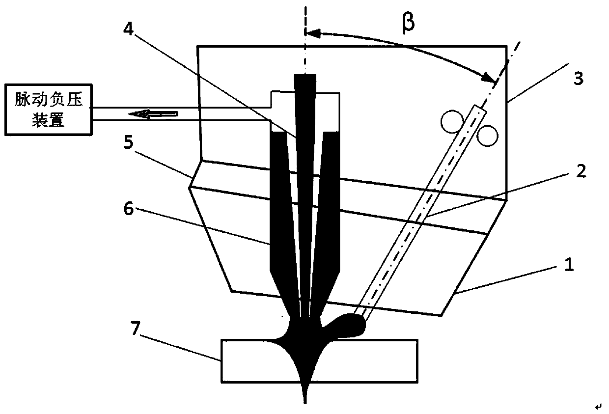
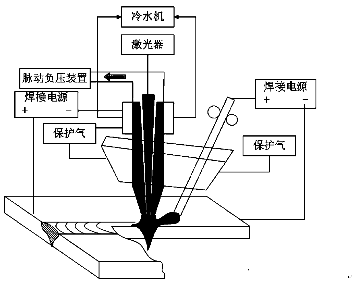
[0023] like Figure 1-2 As shown, the pulsating negative pressure laser-enhanced KTIG and MIG composite welding device includes a hollow tungsten electrode 6 , a laser beam 4 , a MIG welding torch 2 , a welding torch bracket 3 , a shielding gas cover 1 , and a welding base 5 . The pulsating negative pressure device makes the inside of the hollow tungsten electrode 6 reach a state of pulsating negative pressure. The laser beam 4 is generated by the laser and passes through the hollow tungsten electrode 6 to achieve coaxial recombination of the laser beam and the KTIG arc. The hollow tungsten electrode 6 and the MIG welding torch 2 form a KTIG - MIG composite welding torch, the composite welding torch is fixed on the welding base 5 through screw connection, the welding base 5 is fixed on the welding support 3 through bolt connection; the shielding gas cover 1 is fixed on the welding base 5 through screw connection.

[0024] The welding power supply includes KTIG welding power su...


PUM

PropertyMeasurementUnit
wavelengthaaaaaaaaaa
diameteraaaaaaaaaa
diameteraaaaaaaaaa

Abstract

The invention belongs to the technical field of welding equipment, and discloses a pulsating negative pressure laser-enhanced KTIG and MIG composite welding device and method. The device includes a KTIG welding torch, a laser beam, a MIG welding torch, a welding torch bracket, a protective gas cover, a welding base, a cooling water device, The gas feeding device and the pulsating negative pressure device, the laser beam passes through the hollow tungsten electrode of the KTIG welding torch and coaxially combines with the KTIG arc. The KTIG welding torch and the MIG welding torch have a certain angle, which can be adjusted. The welding bracket is fixedly connected, and the protective gas cover is fixedly connected with the welding base. The welding device of the present invention enhances the keyhole characteristics of the KTIG arc through the laser generated by the laser, assists the KTIG to realize stable penetration perforation welding, improves the shape of the arc, changes from a high-angle cup shape to a cone shape, and reduces the heat-affected zone of the weld seam. The pulsating negative pressure device can restrain the arc, make the arc oscillate, improve the structure of the welded joint, optimize the quality of the welded joint, make the weld shape even and delicate, and improve the welding efficiency.

Description

technical field [0001] The patent of the present invention relates to the technical field of welding equipment, in particular to a pulsating negative pressure laser-enhanced KTIG and MIG composite welding device and method. Background technique [0002] In 1997, Australia's CSIRO Research Institute proposed a high-efficiency welding method—Keyhole TIGwelding, referred to as KTIG welding (Patent No. WO 2010 / 045676 A1). More than 6mm, current greater than 300A, KTIG arc energy and arc pressure will be significantly increased, the welding process will form a stable tail hole, forming a perforation welding similar to plasma arc, especially suitable for materials with high surface tension of liquid metal, for medium thickness below 14mm The plate can realize single-sided welding and double-sided forming effect without opening and filling wire, the weld texture is fine, the quality of welded joints and welding efficiency are significantly improved, and the welding cost is greatly ...

Claims


Application Information

Patent Timeline
Patent Type & Authority Patents(China)
IPC IPC(8): B23K26/348B23K26/14B23K26/146B23K26/70
Inventor 于江王波张洪涛桑健高丙路
Owner HARBIN INST OF TECH AT WEIHAI
Learn More