
Switch power source circuit having standby cell for power supply

A switching power supply circuit and backup battery technology, applied in the field of electronics, can solve the problems of consuming the output power of the switching power supply, reducing the energy conversion efficiency of the switching power supply, etc.

Inactive Publication Date: 2018-03-09
谢兴艺
View PDF0 Cites 0 Cited by
  • Summary
  • Abstract
  • Description
  • Claims
  • Application Information

AI Technical Summary

Problems solved by technology

[0002] In the prior art, there is a PWM switching power supply with a backup battery, but its structure usually uses a plurality of diode isolation methods to achieve isolation between two power supply units to prevent mutual backflow between the two power supplies, usually in the battery Two diodes are connected in series to the output terminal of the switching power supply to prevent the switching power supply from charging the battery. At the same time, an isolation diode is connected in series to the output terminal of the switching power supply to prevent the battery current from being poured back into the switching power supply, preventing the battery from rapidly depleting and losing the backup function.
[0003] In view of the increasing requirements for power conversion efficiency in various countries, the existing isolation technology has defects. The isolation diode at the output end of the switching power supply will greatly consume the output power of the switching power supply, greatly reducing the energy conversion efficiency of the switching power supply, and urgently needs to be improved.

Method used


Image

  • Switch power source circuit having standby cell for power supply
  • Switch power source circuit having standby cell for power supply

Examples


Embodiment Construction

[0009] In order to facilitate the understanding of the present invention, the present invention will be described more fully below with reference to the associated drawings. A preferred embodiment of the invention is shown in the drawings. However, the present invention can be embodied in many different forms and is not limited to the embodiments described herein. Rather, these embodiments are provided so that the disclosure of the present invention will be thorough and complete.

[0010] It should be noted that when an element is referred to as being “fixed” to another element, it can be directly on the other element or there can also be an intervening element. When an element is referred to as being "connected to" another element, it can be directly connected to the other element or intervening elements may also be present. The terms "vertical," "horizontal," "left," "right," and similar expressions are used herein for purposes of illustration only.

[0011] Unless otherw...


PUM


Abstract

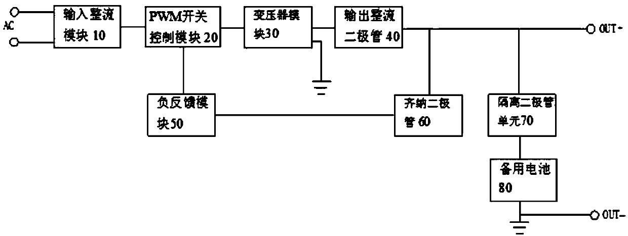
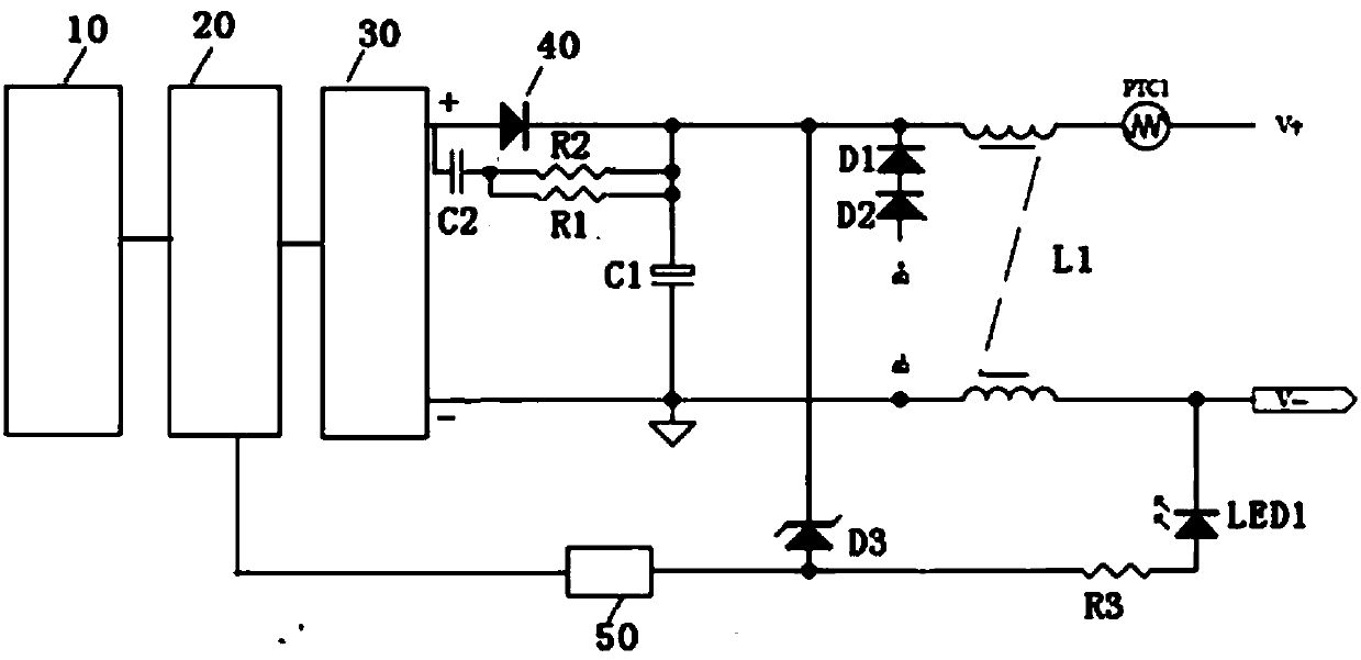
The invention provides a switch power source circuit having a standby cell for power supply. The switch power source circuit having the standby cell for power supply comprises an input rectification module, a PWM switch control module, a transformer module, an output rectification diode, a negative feedback module, the standby cell, an isolation diode unit and a Zener diode, wherein a positive electrode of the output rectification diode is connected with a positive output end of the transformer module, a negative electrode of the output rectification diode is connected with a negative electrode of the isolation diode unit, a positive electrode of the isolation diode unit is connected with a positive electrode of the standby cell, a negative electrode of the standby cell is connected with anegative output end of the transformer module, a negative electrode of the Zener diode is connected between the negative electrode of the isolation diode unit and the negative electrode of the outputrectification diode, one end of the negative feedback module is connected with a positive electrode of the Zener diode, and the other end is connected with a control port of the PWM switch control module. The switch power source circuit is advantaged in that output loss of a switch power source is reduced, and conversion efficiency of the switch power source is improved.

Description

technical field [0001] The invention relates to the field of electronic technology, in particular to a switching power supply circuit with a backup battery. Background technique [0002] In the prior art, there is a PWM switching power supply with a backup battery, but its structure usually uses a plurality of diode isolation methods to achieve isolation between two power supply units to prevent mutual backflow between the two power supplies, usually in the battery Two diodes are connected in series to the output terminal of the switching power supply to prevent the switching power supply from charging the battery. At the same time, an isolation diode is connected in series to the output terminal of the switching power supply to prevent the battery current from being poured back into the switching power supply, preventing the battery from rapidly depleting and losing the backup function. . [0003] In view of the increasing requirements for power conversion efficiency in va...

Claims


Application Information

Patent Timeline
Patent Type & Authority Applications(China)
IPC IPC(8): H02M7/06
CPCH02M7/06H02M1/0048Y02B70/10
Inventor 谢兴艺
Owner 谢兴艺
Learn More