Mobile power supply

A mobile power supply and resistance technology, applied in the direction of collectors, electric vehicles, electrical components, etc., can solve the problems of low reliability, complex structure, high cost, and achieve the effect of high discharge conversion efficiency, simplified circuit, and reduced production cost.

Inactive Publication Date: 2018-03-09
张超
View PDF3 Cites 0 Cited by
  • Summary
  • Abstract
  • Description
  • Claims
  • Application Information

AI Technical Summary

Problems solved by technology

At present, domestic mobile power supply control circuits mostly use analog circuits, which have disadvantages such as complex structure, low reliability, low efficiency and high cost.

Method used


Image

  • Mobile power supply
  • Mobile power supply

Examples


Embodiment Construction

[0011] The present invention will be further elaborated below in conjunction with the accompanying drawings and specific embodiments.

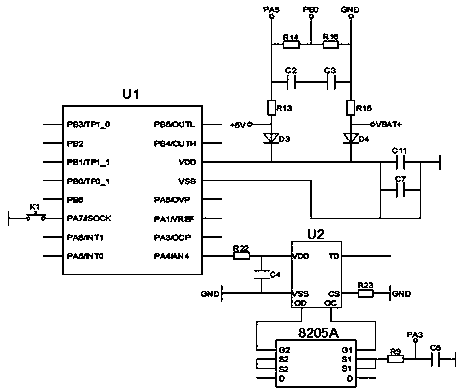
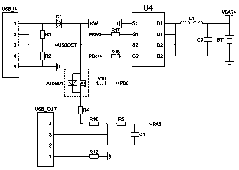
[0012] A mobile power supply, the mobile power supply has a built-in charging and discharging circuit and a control circuit, and the charging and discharging circuit is connected with the control circuit.

[0013] In the charging and discharging circuit, port 1 of the USB input socket is connected to +5V power supply through diode D1, port 1 of the USB input socket is connected to resistor R2 through resistor R1, port 5 of the USB input socket is grounded, and port 5 of the USB input socket is connected to Resistor R4 and diode D1 are connected to the S2 port of the chip U4, while the diode D1 is connected to the resistor R4 through the P-channel enhanced MOS field effect transistor Q1, and the base of the P-channel enhanced MOS field effect transistor Q1 is connected to the chip U1 through the resistor R19 PB6, resistor R4 is connected to the...


PUM


Abstract

The invention relates to a mobile power supply. A charging and discharging circuit and a control circuit are arranged in the mobile power suppl. The charging and discharging circuit is connected withthe control circuit. The first port of a USB input socket in the charging and discharging circuit is connected with a +5 v power source through a diode D1. The first port of the USB input socket is connected with a resistor R2 through a resistor R1. The fifth port of the USB input socket is grounded. The fifth port of the USB input socket is connected with a resistor R4. The diode D1 is connectedwith the S2 port of a chip U4. Meanwhile, the diode D1 is connected with the resistor R4 through a p-channel enhanced MOS field effect tube. The base electrode of the p-channel enhanced MOS field-effect transistor is connected with a PB6 of a chip U1 through a resistor R19. The resistor R4 is connected with the fourth port of a USB output socket.The fourth port of the USB output socket is connected with a resistor R5 through a resistor R10. The resistor R5 is connected with a capacitor C1. Meanwhile, the resistor R5 is connected with the PA5 port of the chip U1. The second port and the third port of the USB output socket are connected with the resistor R5. The mobile power supply is good in safety, stable to run and convenient in operation.

Description

technical field [0001] The invention relates to the field of equipment circuits, in particular to a mobile power supply. Background technique [0002] With the popularization of portable electronic products, mobile power sources are more and more widely used in consumer electronic products. Mobile power generally adopts polymer lithium batteries and DC conversion methods. At present, domestic mobile power supply control circuits mostly use analog circuits, which have disadvantages such as complex structure, low reliability, low efficiency and high cost. Contents of the invention [0003] The purpose of the present invention is to provide a mobile power supply to solve the above technical problems. To achieve the above purpose, the present invention adopts the following technical solutions: [0004] A mobile power supply, the mobile power supply has a built-in charging and discharging circuit and a control circuit, and the charging and discharging circuit is connected wit...

Claims


Application Information

Patent Timeline
Patent Type & Authority Applications(China)
IPC IPC(8): H02J7/00
CPCH02J7/00H02J7/00302H02J7/00304H02J7/00306H02J7/0031H02J7/0068
Inventor 张超
Owner 张超
Why Eureka
Try Eureka