
Rapid lighting adjustment control method for automatic gain control type photoelectric pulse oximeter

A technology of automatic gain control and photoelectric pulse, which is applied in medical science, sensors, diagnostic recording/measurement, etc. It can solve the problems of large differences in test parts, long waveform response time, poor probe compatibility, etc., and achieve stable and reliable waveform quality. The effect of expanding the dynamic range and anti-interference optimization

Inactive Publication Date: 2018-03-09
JIANGSU KONSUNG BIOMEDICAL TECH
View PDF9 Cites 9 Cited by
  • Summary
  • Abstract
  • Description
  • Claims
  • Application Information

AI Technical Summary

Problems solved by technology

[0004] However, the traditional dimming control algorithm has the following problems: 1. The dimming logic used is relatively simple, and the dimming time is long, resulting in a long waveform response time; 2. It is susceptible to interference when dimming under sports conditions; 3. There is no automatic gain adjustment function. Due to the large differences in the test sites of different subjects, the same probe is not effective in special occasions (such as very thick or very thin fingers), and the performance of probes from different manufacturers is different. If there is no gain adjustment function, the adjustable dynamic range of the PPG signal is small, and the compatibility with the probe is also poor
Therefore, the defect of this traditional algorithm is very obvious, and it cannot meet the fast response required by the standard.

Method used


Image

  • Rapid lighting adjustment control method for automatic gain control type photoelectric pulse oximeter
  • Rapid lighting adjustment control method for automatic gain control type photoelectric pulse oximeter
  • Rapid lighting adjustment control method for automatic gain control type photoelectric pulse oximeter

Examples


Embodiment Construction

[0030] The preferred embodiments of the present invention will be further described in detail below in conjunction with the accompanying drawings.

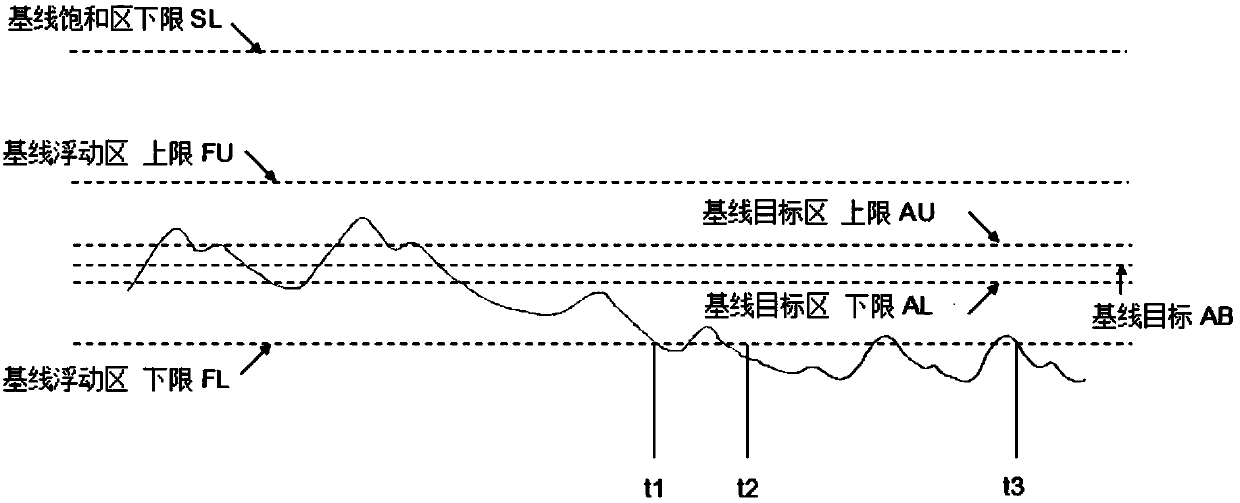
[0031] Calculating the blood oxygen parameters requires processing the PPG signal to separate the DC and AC components. In order to obtain a better dynamic range and SNR, it is necessary to use a stable light source and adjust the PPG signal to the target range. In the current design, the light source generally adopts LED, which has better monochromaticity and stability.

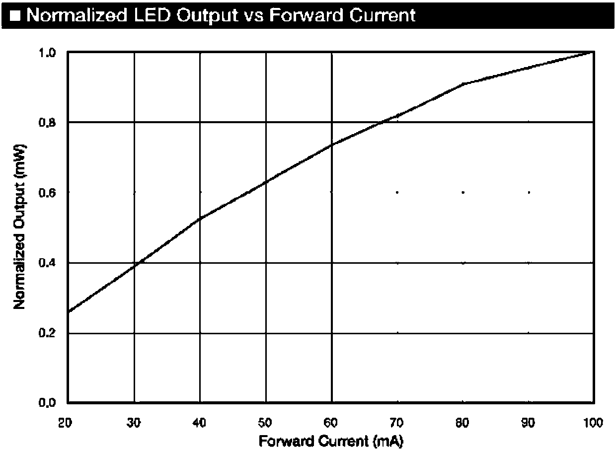
[0032] The conventional dimming algorithm uses a DC baseline locking algorithm that adjusts the DC component to the target area. Most algorithms regard the luminous intensity and driving current of the LED as a linear relationship, and predict the light intensity to adjust the DC intensity (ie, the baseline position). However, according to the actual test of the manufacturer, the luminous intensity and driving current of the LED can only maintain linearity in a...


PUM


Abstract

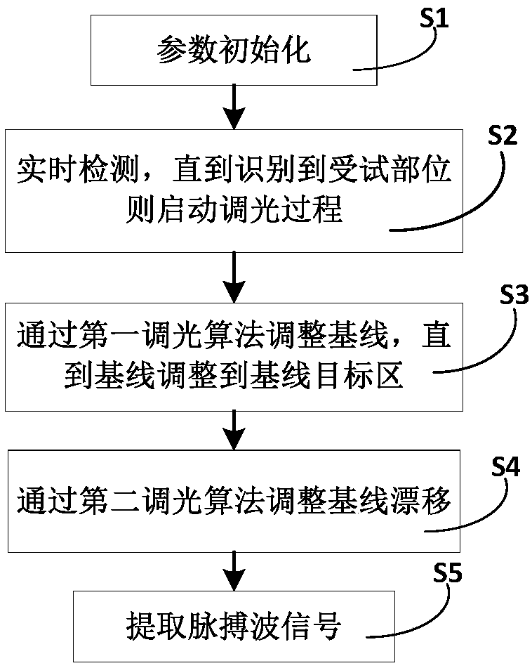
The invention provides a rapid lighting adjustment control method for an automatic gain control type photoelectric pulse oximeter. The method comprises the following steps: (S1) carrying out parameterinitialization; (S2) carrying out real-time detection until a tested part is recognized, adjusting a driving current to a default value, and starting a lighting adjustment process; (S3) adjusting a baseline by virtue of a first lighting adjustment algorithm until the baseline is adjusted to a base line target region; (S4) adjusting baseline drift by virtue of a second lighting adjustment algorithm; and (S5) extracting a pulse wave signal. According to the method, the rapid lighting adjustment can be realized, the range of the dynamic adjustment is expanded through automatic gain, so that themethod can be well compatible with various types of probes; and meanwhile, the interference resistance is optimized under a motion condition, so that high-quality PPG signal data are provided for thesignal processing of photoelectric pulse waves. Experiments prove that the waveform response speed of the method can be decreased from 5-6 seconds in the prior art to be within 3 seconds, waveform breakpoints and lighting adjustment trigger are fewer under the motion condition, and the waveform quality is stable and reliable.

Description

technical field [0001] The invention relates to a dimming control method for a photoelectric pulse oximeter, in particular to a fast dimming control method for a photoelectric pulse oximeter with automatic gain control. Background technique [0002] The traditional photoelectric pulse oximeter adopts the principle of photoelectric detection, which uses light of a specific wavelength to transmit or reflect from the surface of human tissue, and extracts the photoplethysmogram (PPG) signal of incident light and received light, and then detects Blood oxygen parameters are calculated. A common method is to use a probe with a light source and a photoelectric detector to detect weaker parts of the human body such as fingers, earlobes, and forehead. [0003] At present, in the blood oxygen algorithm, it is first necessary to control the light source to obtain a better transmission or reflection signal, and the signal is required to be stable. In addition, in order to meet the requ...

Claims


Application Information

Patent Timeline
Patent Type & Authority Applications(China)
IPC IPC(8): A61B5/1455
CPCA61B5/14551A61B5/14552A61B5/7225
Inventor 李笑涛王一岳之恒
Owner JIANGSU KONSUNG BIOMEDICAL TECH
Learn More