FPGA-based onboard system realization method

A technology for equipment and processor modules, which is applied to architectures, instruments, and general-purpose stored-program computers with a single central processing unit. The effect of high flexibility and flexible computer system hardware

Inactive Publication Date: 2018-03-06
ZHEJIANG UNIV
View PDF2 Cites 3 Cited by
  • Summary
  • Abstract
  • Description
  • Claims
  • Application Information

AI Technical Summary

Problems solved by technology

This kind of work is too delicate, and it is easy to cause the overall system operation not to meet expectations due to improper handling of individual signal lines. At the same time, it increases the difficulty of debugging.

Method used


Image

  • FPGA-based onboard system realization method
  • FPGA-based onboard system realization method

Examples


Embodiment Construction

[0029] In order to facilitate those skilled in the art to better understand the present invention, the present invention will be described in further detail below in conjunction with the accompanying drawings and specific embodiments. The following is only exemplary and does not limit the protection scope of the present invention.

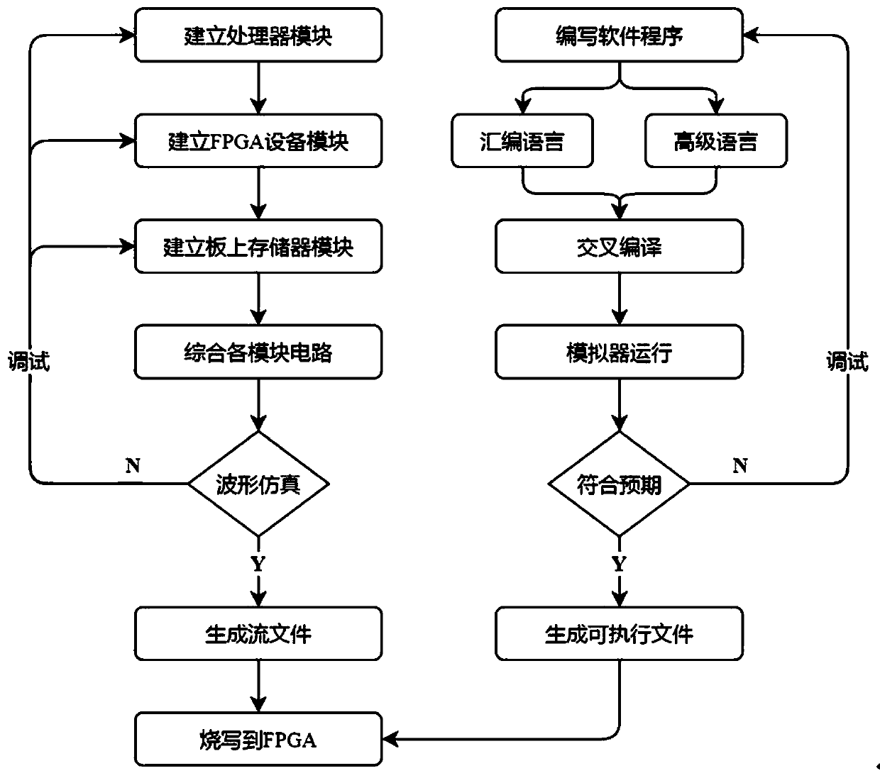
[0030] A kind of FPGA-based system implementation method on board of the present invention, such as figure 1 and 2 shown, including the following steps:

[0031] S1. Establishing a processor module: the processor module includes a controller and a data path.

[0032] In the step S1, the internal connection mode of the processor module is: the controller and the data path are connected through an on-chip network.

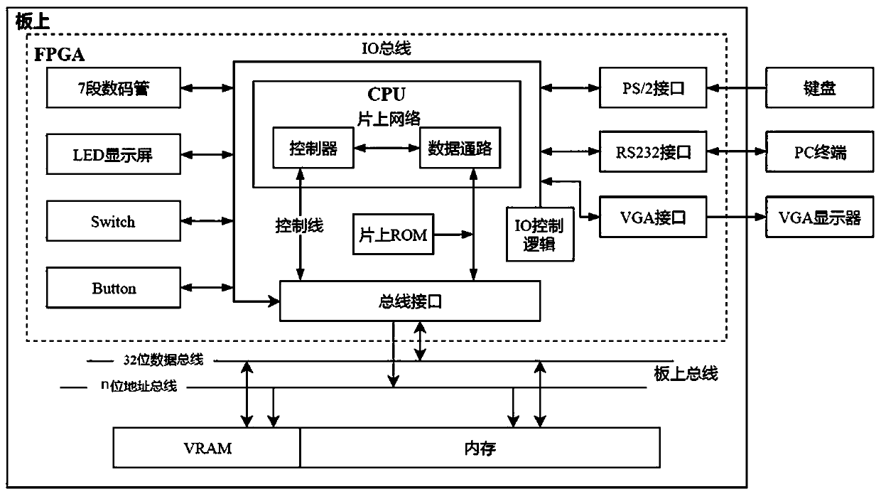
[0033] S2. Establish FPGA device module: the FPGA device module includes PS / 2 interface, RS232 interface, VGA interface, 7-segment LED display, LED display, Switch, Button, on-chip ROM, bus interface and IO control logic.

[0034] In t...


PUM


Abstract

The invention discloses an FPGA-based onboard system realization method. The method comprises the steps of S1, establishing a processor module, wherein the processor module comprises a controller anda data path; S2, establishing an FPGA device module, wherein the FPGA device module comprises a PS / 2 interface, an RS232 interface, a VGA interface, a 7-section LED display screen, an LED display screen, a Switch, a Button, an on-chip ROM, a bus interface and IO control logic; S3, establishing an onboard memory module, wherein the onboard memory module comprises a VRAM and a memory; and S4, combining circuits of the processor module, the FPGA device module and the memory module into a stream file, and programming the stream file in an FPGA. The method has the advantages in two aspects that therealization efficiency is high: hardware resources provided by the FPGA are rich, and designed computer system hardware can be quickly realized on the FPGA, so that the realization efficiency is higher; and the flexibility is high: the FPGA is reconfigurable, so that when partial hardware parameters of the computer system hardware are changed, reconfiguration can be performed during operation, namely, the computer system hardware realized through the FPGA is more flexible.

Description

technical field [0001] The invention relates to an implementation method of an FPGA-based system on board, and belongs to the technical field of computer system hardware. Background technique [0002] Since the beginning of the 21st century, the advancement of semiconductor technology and the demand for high-performance computing have promoted the rapid development of computer systems, and the architecture of processors has undergone tremendous changes. As the core component of the computer, the performance improvement of the processor is largely due to the progress of the semiconductor process and the development of the system structure. The progress of the semiconductor process and the development of the system structure have always been in a relationship of mutual promotion, the former is the basis of the latter, and the latter promotes the former. Every change in the development of the architecture is accompanied by a breakthrough in the number of integrated transistors...

Claims


Application Information

Patent Timeline
Patent Type & Authority Applications(China)
IPC IPC(8): G06F15/78
CPCG06F15/7803
Inventor 陈文智施青松王总辉
Owner ZHEJIANG UNIV
Why Eureka
Try Eureka