
Charging device for 3D printing equipment

A feeding device and 3D printing technology, applied in the field of 3D printing, can solve the problems of inaccurate quantification, slow forming speed, slow feeding, etc., to achieve the effect of ensuring processing quality, consistent output position, and high processing efficiency

Inactive Publication Date: 2018-03-06
立方通达(天津)实验仪器有限公司 +1
View PDF4 Cites 7 Cited by
  • Summary
  • Abstract
  • Description
  • Claims
  • Application Information

AI Technical Summary

Problems solved by technology

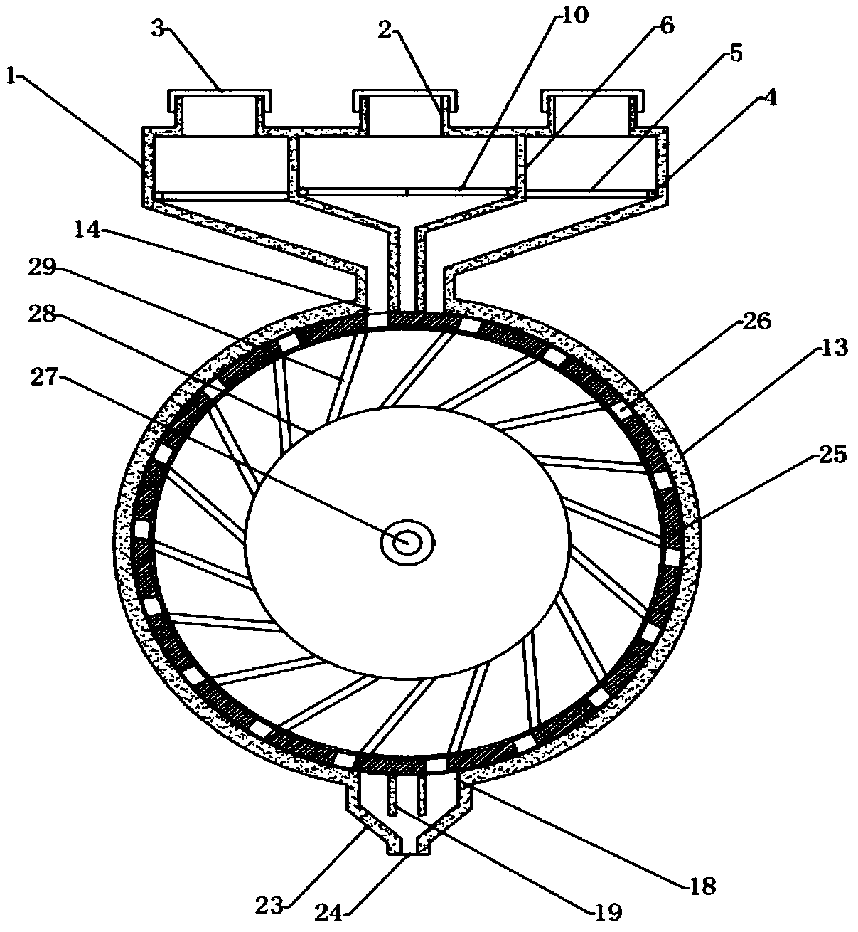
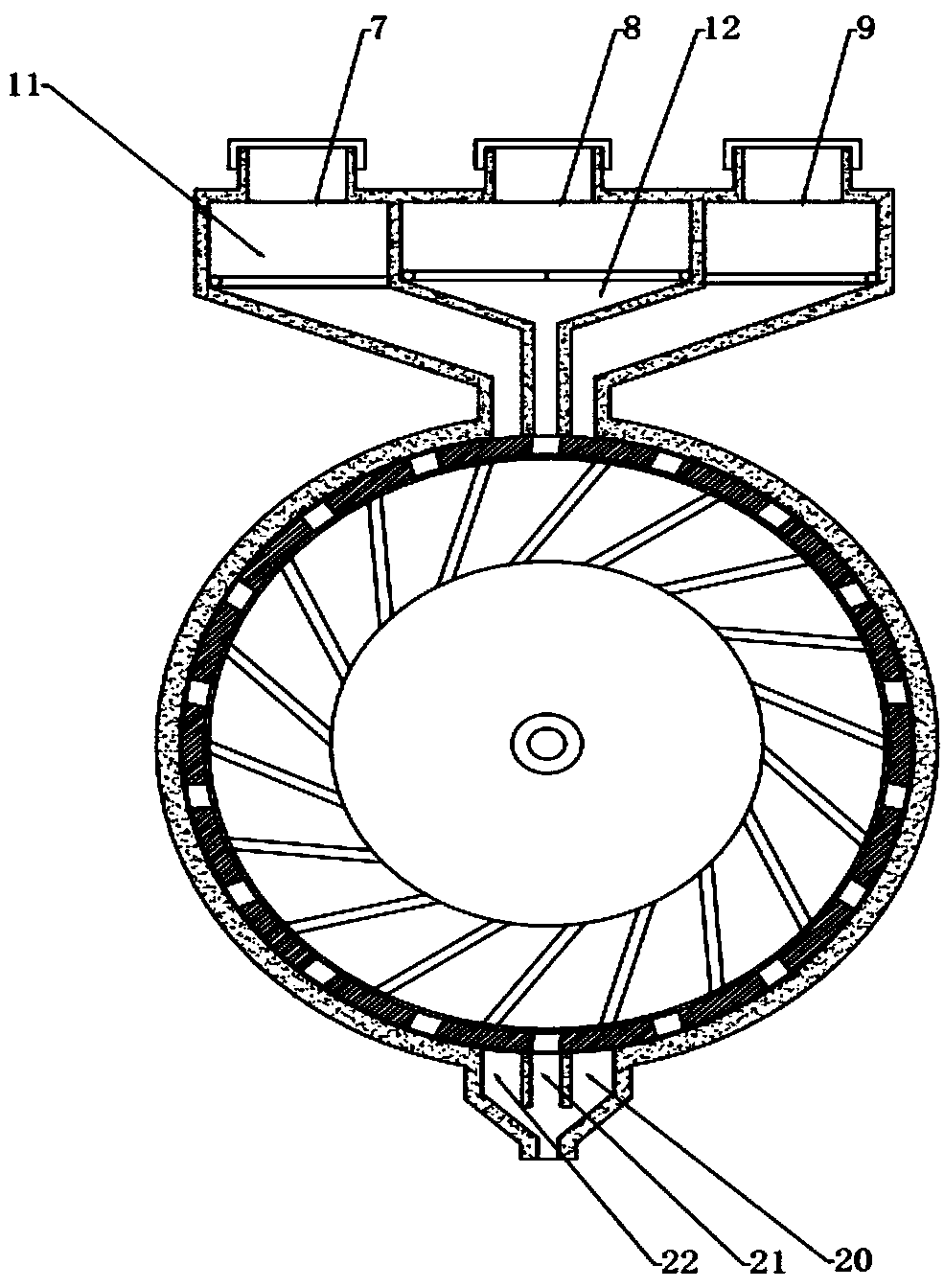
[0002] 3D printing is a kind of rapid prototyping technology. It is a technology based on digital model files and using bondable materials such as powdered metal or plastic to construct objects by layer-by-layer printing. The existing 3D printing The feeding device of the equipment is not accurate in quantification, and it is easy to cause slow feeding during the feeding process, which affects the speed of 3D printing, and the feeding speed of the feeding device is uneven, which has a certain adverse effect on the quality of the printed product. The publication number is CN206085694U The Chinese patent discloses a feeding device for 3D printing equipment. By adding drive rollers and quantitative partitions to the quantitative feeding device, the powder is delivered quantitatively, and the feeding is more uniform. However, the disadvantage is that the selection of raw materials is not flexible enough. , the various parts or products that actually need 3D printing are rarely composed of a single material. If the workpiece is a composite part, the same machine cannot be used. If a workpiece needs to add other materials or use different colors and different types of raw materials, the factory It is necessary to prepare more than two sets of processing equipment, which not only costs a lot of investment, but also takes up more factory space for the increase of equipment, and the forming efficiency of the workpiece is low, and the forming speed is slow

Method used


Image

  • Charging device for 3D printing equipment
  • Charging device for 3D printing equipment
  • Charging device for 3D printing equipment

Examples


Embodiment Construction

[0028] First of all, it should be noted that the specific structure, features and advantages of the feeding device of the 3D printing equipment of the present invention will be specifically described below by way of example, but all descriptions are for illustration only, and should not be Any limitations on the invention are understood to be construed. In addition, any single technical feature described or implied in each embodiment mentioned herein, or any single technical feature shown or implied in each drawing, can still be described in these technical features (or their equivalents) ) to continue any combination or deletion, so as to obtain more other embodiments of the present invention that may not be directly mentioned herein. In addition, for the sake of simplifying the drawings, the same or similar technical features may only be marked in one place in the same drawing.

[0029] In the description of the present invention, it should be noted that the orientation or ...


PUM


Abstract

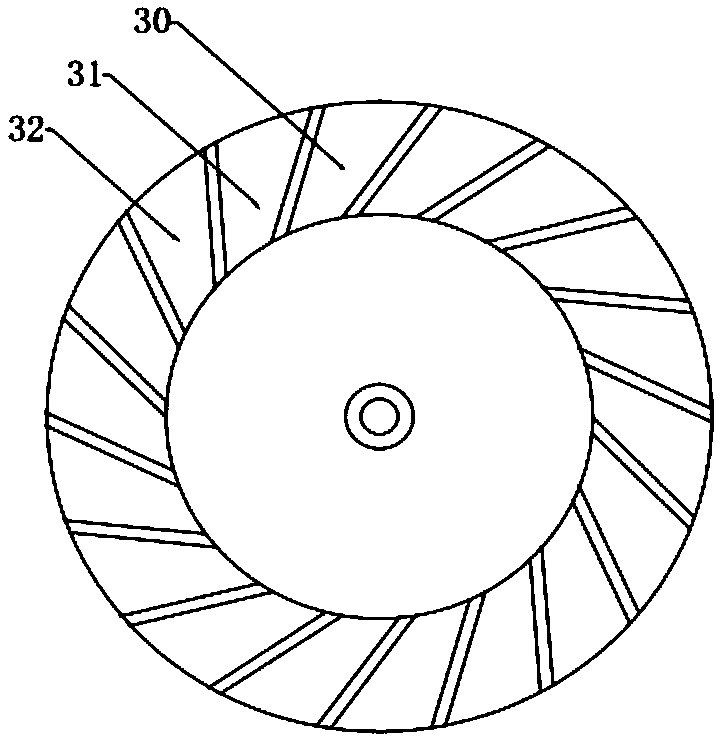
The invention relates to a charging device for 3D printing equipment. A primary partition board divides the material storage tank into a primary stock bin, a secondary stock bin and a tertiary stock bin, wherein a primary baffle is arranged in the primary stock bin and the tertiary stock bin, a pair of secondary baffles are symmetrically arranged in the secondary stock bin, the primary baffle andthe secondary baffles respectively divide the primary stock bin, the secondary stock bin and the tertiary stock bin into a material storage bin and a material charging bin which are distributed up anddown, a transmission roller is arranged in a feeding box, the outer side of the transmission roller is fixedly connected with a plurality of quantitative partition boards, a material distributing binis formed between two adjacent quantitative partition boards, a material distributing box is arranged between the quantitative partition boards and the feeding box, a plurality of material distributing holes are formed in the material distributing box, a secondary partition board is arranged at a discharging hole, the secondary partition board divides the discharging hole into a primary discharging hole, a secondary discharging hole and a tertiary discharging hole, a discharging pipe is fixedly connected below the discharging hole, and the bottom of the discharging pipe is a feeding hole. Thecharging device for the 3D printing equipment can be applicable to charging of multiple materials or multicolor raw materials and is simple in structure and high in processing efficiency.

Description

technical field [0001] The invention relates to the technical field of 3D printing, in particular to a feeding device for 3D printing equipment. Background technique [0002] 3D printing is a kind of rapid prototyping technology. It is a technology based on digital model files and using bondable materials such as powdered metal or plastic to construct objects by layer-by-layer printing. The existing 3D printing The feeding device of the equipment is not accurate in quantification, and it is easy to cause slow feeding during the feeding process, which affects the speed of 3D printing, and the feeding speed of the feeding device is uneven, which has a certain adverse effect on the quality of the printed product. The publication number is CN206085694U The Chinese patent discloses a feeding device for 3D printing equipment. By adding drive rollers and quantitative partitions to the quantitative feeding device, the powder is delivered quantitatively, and the feeding is more unifo...

Claims


Application Information

Patent Timeline
Patent Type & Authority Applications(China)
IPC IPC(8): B29C64/336B22F3/00B33Y40/00B22F12/52
CPCB22F3/005B33Y40/00
Inventor 李芳高彦成马国伟王里
Owner 立方通达(天津)实验仪器有限公司
Learn More