Chip unit with specific driving modes and for combined detection of six main tumor markers

A technology of tumor markers and driving methods, which is applied in the field of chip devices for the joint detection of the main six tumor markers, and can solve the troublesome operation of modifying the inner surface of the PDMS channel, channel bubbling substrate and cover sheet, large flow resistance, etc. question

Inactive Publication Date: 2018-03-06
蒋剑萍
View PDF4 Cites 0 Cited by
  • Summary
  • Abstract
  • Description
  • Claims
  • Application Information

AI Technical Summary

Problems solved by technology

[0008] But it's not that simple
[0009] First, this polydimethylsiloxane material, which is referred to by the acronym PDMS, is itself a strongly hydrophobic material, and channels are built on this material. modification operation, then, after the overall assembly is completed, that is, after the cover is covered, because the inner surface of the channel in the structure occupies most of the inner surface of the liquid flow channel, then the inner surface of the PDMS channel is The strong hydrophobicity is the decisive factor, it will make it very difficult for the polar liquid fine flow similar to the aqueous solution to pass through, and its flow resistance is so large that even the general micropump is difficult to push, of course, if the cover sheet is also If you choose to use the PDMS material, then the problems are basically the same, with minor differences; therefore, in the prior art, it is necessary to modify and modify the inner surface of the channel on the PDMS material; then, this is for the PDMS channel Is the modification operation of the inner surface of the channel very troublesome? That's not the problem. What constitutes a serious technical problem is another problem: the PDMS polymer molecules in the bulk phase of the PDMS material substrate have the characteristics of automatic diffusion and migration to the surface. The characteristics of polymer molecules diffusing and migrating to the surface automatically will make the modified state of the inner surface of the channel modified by the surface unable to maintain for a long enough time. The maintenance time of the internal surface state is roughly only enough to complete the time required for the internal test experiment in the laboratory; in other words, the surface state of the PDMS channel inner surface after surface modification or surface modification is formed after modification It cannot last for a long time, but it will automatically tend to or change back to the surface state before the surface modification, and return to the original strongly hydrophobic surface state in a short period of time. Then, just imagine, such a slight Can flow control chips be produced in large quantities, stored in large quantities, and widely promoted? The answer is obvious, that is, impossible
[0018] Third, as mentioned above, the inner surface of the PDMS channel is strongly hydrophobic, and targeted surface chemical modification or surface chemical modification is difficult to last. It is effective to use it within a short period of time; if the relatively short expiration date has passed and it is still used forcibly, since the surface state is already close to the hydrophobic state, there must be a relatively large liquid flow driven by the conventional micropump. In this way, the sample liquid can only be forced to flow in the target direction by increasing the pumping power and pumping pressure of the micropump. Sending pressure to pump the sample liquid flow will cause bubbling, puffing, twisting, and deformation of the channel at the sampling end of the substrate, including the area near the sampling end, and, under such high pressure conditions, in the The channel and its periphery at the injection end and its vicinity are also prone to peeling between the substrate and the cover slip. In this case, the sample solution will enter the gap between the substrate and the cover slip formed after the peeling. This actually leads to the damage of the microfluidic chip; of course, if the surface modification or surface modification is not in place, it will also lead to the above-mentioned situation within the short customary validity period; In the case of an external micropump for liquid flow drive, the above-mentioned problem always exists
As mentioned above, if no pre-operations such as surface modification or surface modification have been done at all, then the above-mentioned problem will be more serious, even if there is no channel bubbling at the injection end and its vicinity, Problems such as puffing, twisting, deformation, and peeling between the substrate and the cover sheet, etc., just because the flow resistance is too large, the use of a high-pressure micropump may not be able to drive the sample liquid flow toward the terminal.

Method used


Image

  • Chip unit with specific driving modes and for combined detection of six main tumor markers

Examples


Embodiment Construction

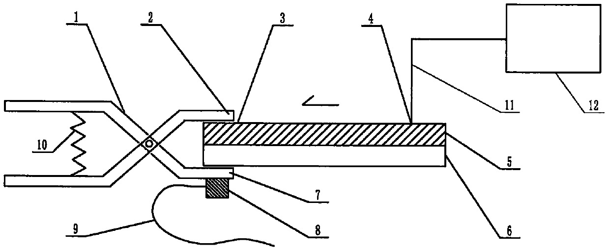
[0076] exist figure 1In the example shown in this case, the main point of this example is that the structure of the device includes a microfluidic chip, and the structure of the microfluidic chip includes a substrate 5 and a cover sheet 6 that are attached to each other and installed together. The base sheet 5 and the cover sheet 6 are both plates or sheets, and the surface of the base sheet 5 facing the cover sheet 6 contains a channel structure formed by a molding process or an etching process, and is mounted on the Together, the substrate 5 and the cover sheet 6 have jointly constructed a microfluidic chip containing a pipe structure, and the structural position of the pipe is located at the junction area where the substrate 5 and the cover sheet 6 are attached to each other. The ports are respectively connected to the sampling port 4 and the terminal 3 of the microfluidic chip, the sampling port 4 is the injection port of the sample solution of the microfluidic chip, and t...


PUM

PropertyMeasurementUnit
thicknessaaaaaaaaaa
particle diameteraaaaaaaaaa
diameteraaaaaaaaaa

Abstract

The invention relates to a chip device for combined detection of six main tumor markers with a specific driving mode, which belongs to the field of analysis and testing. Polydimethylsiloxane, or PDMS, is used to make the substrate of a microfluidic chip for multi-channel joint detection of typical tumor markers, and there are difficulties. The main point of this case is that the PDMS with the original ecological surface is selected for the substrate, and the elastic clip with the micro-ultrasonic transducer attached to the clamping arm is positioned at the terminal position of the sample liquid flow of the chip by elastic snapping. The driving force based on the difference in interfacial tension is formed, and at the same time, it is coupled with the driving force of the micropump to jointly drive the sample liquid to flow in the direction of the terminal. The pipeline of the chip is filled with micron-sized silica particle fillers. The functions include supporting the inner wall of the pipeline, compensating the originally hydrophobic pipeline with a collection of hydrophilic micro-channels, and squeezing and covering the inner wall of the pipeline so as to reduce the chance of biomacromolecules contacting the inner wall.

Description

technical field [0001] The invention relates to a chip device for combined detection of six main tumor markers with a specific driving mode, which belongs to the field of analysis and testing. Background technique [0002] Tumor markers (tumor markers, TM) refer to a class of substances produced by tumor cells themselves or produced by the body's response to tumor cells during the occurrence and proliferation of tumors, reflecting the existence and growth of tumors, including Proteins, hormones, enzymes (isoenzymes) and oncogene products, etc. Testing the tumor markers in the patient's blood or body fluids can detect tumors early in the tumor screening, observe the curative effect of tumor treatment and judge the prognosis of patients. Currently, the tumor markers commonly used clinically are: (1) alpha-fetoprotein (AFP) is a marker for primary liver cancer, testicular cancer, ovarian cancer and other tumors; (2) carcinoembryonic antigen (CEA) is a marker for digestive syst...

Claims


Application Information

Patent Timeline
Patent Type & Authority Applications(China)
IPC IPC(8): B01L3/00G01N33/574
CPCB01L3/50273B01L3/502715B01L2200/10B01L2300/0838B01L2300/0887B01L2300/12B01L2300/161B01L2400/0439B01L2400/0475G01N33/57484
Inventor 李榕生葛宇杰蒋剑萍葛光奇
Owner 蒋剑萍
Why Eureka
Try Eureka