
Drilling and grouting construction method for sand gravel stratum

A technology of sand and gravel and stratum, applied in the direction of foundation structure engineering, sheet pile wall, construction, etc., can solve the problems of low construction efficiency, difficult operation, affecting the grouting effect, etc., and achieve the effect of simplifying the difficulty of installation and operation

Active Publication Date: 2018-03-02
SINOHYDRO BUREAU 11 CO LTD
View PDF4 Cites 4 Cited by
  • Summary
  • Abstract
  • Description
  • Claims
  • Application Information

AI Technical Summary

Problems solved by technology

[0019] 3.1 There are limitations in the grouting of flower tubes. The thick-walled seamless steel pipes with flower tubes are used for grouting of flower tubes to directly drive into the ground to be irrigated, and a bottom-up method is adopted. After a section is filled, a section is pulled out. Casing, pouring the upper section, repeating the extubation and grouting until the grouting of the foundation of the gravel layer is completed
[0021] 2) When a large intubation force is adopted, it is easy to cause the flower tube to be broken and bent, and it is not suitable for the construction in the deep section of the sand and gravel stratum.
[0023] 4) In the process of flower tube insertion, when there are boulders and other large-sized gravels in the stratum, it is difficult to insert the flower tube to the designed position due to the obstruction of the stones at the bottom of the flower tube
[0024] 3.2 The grouting effect of the casing following up the retaining wall and segmental plugging affects the grouting effect in the stratum with a large fine particle content
However, this construction process requires the casing to be pulled up and left the grouting section before grouting can be carried out. If the hole collapses during the pulling out process, the slag collapsed in the hole will form a barrier and barrier, and the upper and lower boundary conditions of the grouting section will be different. For the same grouting segment, the lower half is affected by slag shielding, and the grouting quality is difficult to be guaranteed, especially when there is a lot of fine particles in the formation, the impact will be more serious
[0026] 3.3 Analysis of the existing problems of grouting with mud-solidified, segmented from top to bottom, orifice closed grouting: 1) Mud is used for wall-solidified drilling, and in the process of wall-solidified with clay slurry or the thinnest grade of cement-clay slurry, the mud flows into sand and gravel After the porosity, the groutability of the formation is changed, and the diffusion range of the grout is also reduced. The strength of the locally poured mud in the formation is not enough to meet the design requirements
2) The length of the grouting section is generally 1-3m, and the lower limit is 1m for the formation that is prone to collapse and serious leakage. If necessary, the section length is shortened to 0.5m, which increases the length of the grouting cycle section and lowers the construction efficiency.
[0028] 1) The drilling diameter is required to be 2-3 grades larger than the pre-embedded flower tube, that is, the drilling diameter is required to be more than 130-150mm, which increases the difficulty of drilling and drilling with the tube
[0029] 2) The process is relatively complicated. Drilling a thick-diameter flower tube and filling it is equivalent to the second hole-forming operation, and it is more difficult than the first hole-forming operation. First, it must be ensured that the hole wall will not collapse when the flower tube is built in, which is convenient Downpipe or filler; secondly, the sleeve valve should be made on the flower tube according to the "sleeve valve" grouting method, and the filler should be equipped with open-loop and shell-breaking filler. The filler should have low water separation, good stability, and small underwater condensation shrinkage , Early strength growth is fast, late strength growth is slow, stones are brittle, etc.
Therefore, in the actual sand and gravel grouting construction, seldom use

Method used


Image

  • Drilling and grouting construction method for sand gravel stratum

Examples


Embodiment 1

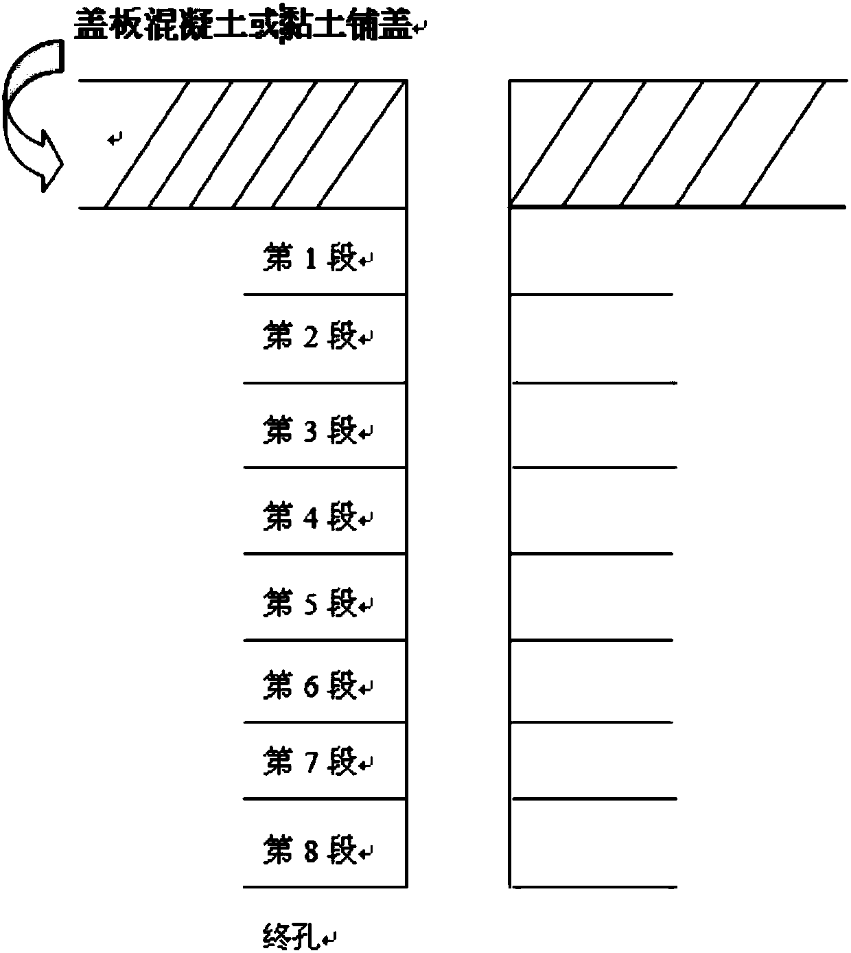
[0064] like figure 1 As shown, the method includes:

[0065] (1) After drilling to the specified depth, follow the pipe to drill into the wall casing; or first use the pipe to drill to send the wall casing to the predetermined depth, and then use the coring method to remove the sand and gravel in the pipe. Until the casing is down to the depth of the grouting segment.

[0066] (2) After the drilling and casing construction is completed, flush the drilling hole, lower the grouting pipe, and pull the bottom of the casing to the top of the grouting section. Rigid plastic tube with floral tube and wrapped with non-woven fabric, the set section length is 5m.

[0067] (3) Install an orifice blocker on the upper part of the grouting pipeline, that is, insert the rubber ring with a hole in the center into a 1.0m double-layer grouting pipe with a bottom support. The diameter of the outer pipe is 50mm, and the diameter of the inner pipe is the same as that of the grouting pipeline. T...

Embodiment

[0079] The strata in a certain place are Quaternary alluvium (alQ4) clay, silt and gravel from top to bottom, and the underlying bedrock is the Lower Tertiary Xinyu Group (E1-2xn) composite conglomerate and gravel strata It is medium or above dense formation, 2-4cm gravels account for 65%, other fillers account for 35%, and the maximum particle size is 6-8cm. When the water level was stored at an elevation of 46.5m, a bubble spring with a diameter of about 5-8cm appeared behind the embankment, and a large area was flooded. For this reason, it is decided to take grouting measures to reinforce the gravel strata where the design spacing of pendulum spraying is 1.4m.

[0080] During the sand and gravel foundation grouting construction process, through the sand and gravel stratum technology test, it was found that: 1) when the method of inserting flower tubes was adopted for construction, the grouting channel was blocked by the fine sand entering the flower tube, so that the sand a...


PUM


Abstract

The invention belongs to the technical field of civil engineering, and relates to a drilling and grouting construction method for a sand gravel stratum. The drilling and grouting construction method for the sand gravel stratum comprises the following steps that firstly, hole drilling is carried out, and pipe following drilling is conducted for downward feeding of a wall protection casing pipe; secondly, a grout pipe line is downwards fed; thirdly, an orifice blocking device is installed; fourthly, according to grouting procedures, a proper water cement ratio is adopted for grouting and grout proportioning changing till grouting completion; and fifthly, grouting construction is carried out. The drilling and grouting construction method for the sand gravel stratum has the beneficial effectsthat the problems caused when a perforated pipe enters the sand gravel stratum are solved; the setting depth is controllable, and compared with an inserting and beating method, the drilling and grouting construction method is easy to conduct; the problem that in the process of pulling out the casing pipe, the sand gravel stratum collapses, and consequently the perforated pipe is blocked is prevented, and the problem that slip casting cannot be effectively conducted in the sand gravel stratum is solved; the installation and operation difficulty of a stop-grouting plug is lowered; the effect onthe grouting diffusion radius is relatively small; the process defects are overcome, and the grouting quality is reliable; and the drilling and grouting construction method is suitable for any sand gravel stratum, can be implemented without process tests and has very obvious beneficial effects for a region where the stratum is complex.

Description

technical field [0001] The invention belongs to the technical field of civil engineering, and relates to a drilling and grouting construction method for sand and gravel formations. Background technique [0002] 1 The main methods of drilling grouting in sand and gravel formations. At present, when grouting sand and gravel formations at home and abroad, the following methods are usually adopted: 1) Grouting with flower tubes; Bottom-up (top-down) segmental plugging grouting; 3) mud wall solidification, top-down segmental, orifice sealing grouting; 4) pre-embedded flower tube grouting, etc. [0003] 2 The main methods and principles of grouting construction in sand and gravel strata are as follows: [0004] 2.1 Grouting for flower tubes: [0005] Grouting with flower tubes is to drive the thick-walled seamless steel pipe with flower tubes directly into the irrigated stratum, and use it to directly connect to the grout delivery pipeline for grouting. The main construction met...

Claims


Application Information

Patent Timeline
IPC IPC(8): E02D15/04E02D5/38C04B28/00C04B111/70
CPCC04B28/00C04B2111/70E02D5/385E02D15/04C04B14/104C04B18/08C04B14/06C04B12/04C04B14/10
Inventor 陈敦刚龚妇容邓小峰卢代权金光有
Owner SINOHYDRO BUREAU 11 CO LTD
Learn More