Eureka AIR delivers breakthrough ideas for toughest innovation challenges, trusted by R&D personnel around the world.

Novel production line and production process for borosilicate glass

A borosilicate glass and production process technology, applied in glass production, glass molding, glass manufacturing equipment and other directions, can solve the problems of high labor intensity, low production efficiency, low labor efficiency, etc., and reduce labor occupation and efficiency. The effect of improving and improving production efficiency

Inactive Publication Date: 2018-02-23
魏云雷
View PDF1 Cites 2 Cited by
  • Summary
  • Abstract
  • Description
  • Claims
  • Application Information

AI Technical Summary

Problems solved by technology

[0004] During the production process, it is necessary to repeatedly clamp and disassemble the borosilicate glass inner container and borosilicate glass outer container, and then heat them to the softening temperature of borosilicate glass for sealing after cooling down and cleaning. The production cycle is very long, the heat energy is wasted seriously, and the labor intensity is high. , low labor efficiency, low production efficiency

Method used


Image

  • Novel production line and production process for borosilicate glass
  • Novel production line and production process for borosilicate glass
  • Novel production line and production process for borosilicate glass

Examples


Embodiment 1

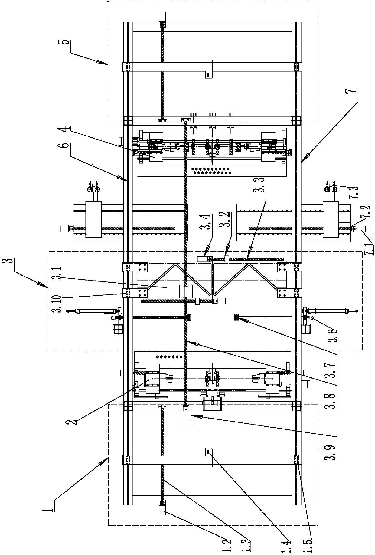
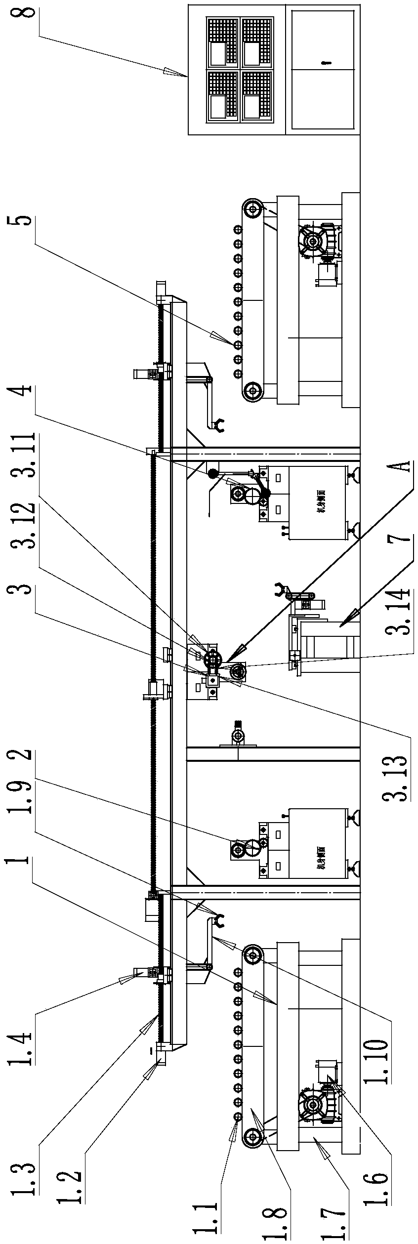
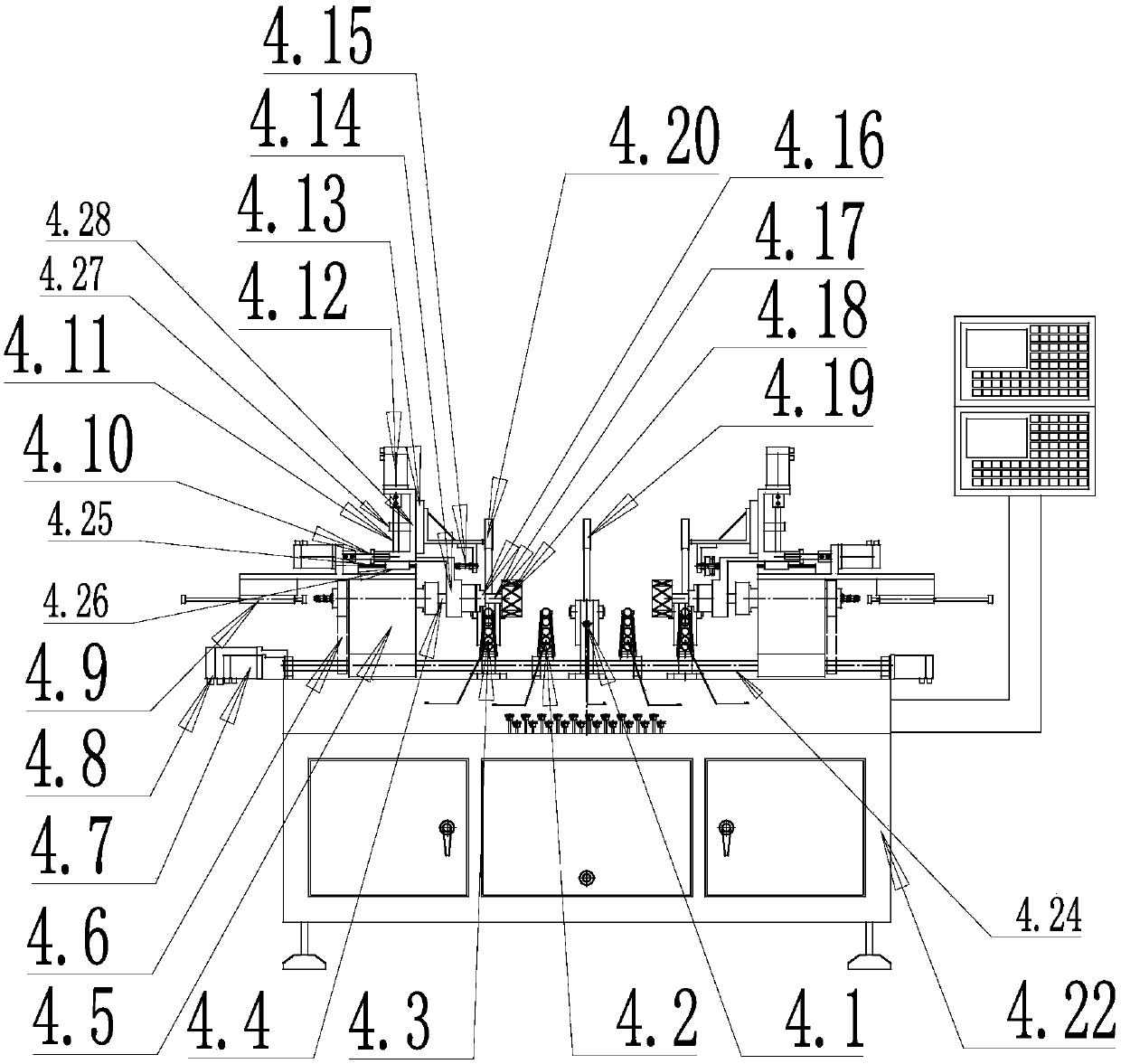
[0077] Such as Figure 1 to Figure 6 As shown, the novel borosilicate glass production line of the present invention includes a slide rail 6, a cleaning device 3 is arranged on the slide rail 6, and a bottom cutting device 2 and a bottom cutting, pressure, diameter and sealing integrated device 4 are arranged side by side under the slide rail 6. The bottom-cutting device 2 and the bottom-cutting, diameter-pressing and sealing-integrated device 4 are respectively located on both sides of the cleaning device 3 .

[0078] The cleaning device 3 includes a mobile clamping assembly, the mobile clamping assembly is arranged on the slide rail 6, and the bottom of the slide rail 6 is provided with a first cleaning fire head 3.7; the mobile clamping assembly 3.2 includes a mobile frame 3.1, and the mobile frame 3.1 is provided with a sliding The sliding block 3.10 that the rail 6 cooperates, the bottom of the mobile frame 3.1 is provided with a clamping assembly. The moving frame 3.1 c...

Embodiment 2

[0080] Such as Figure 1 to Figure 6 As shown, the clamping component is an external clamping component; the first cleaning fire head 3.7 is a built-in first cleaning fire head, and the built-in first cleaning fire head is a ring-shaped built-in first cleaning fire head, and the nozzles of the built-in first cleaning fire head are arranged radially; The built-in first cleaning fire head communicates with the air guide rod 3.6; the outer clamping assembly is connected with the first rotary drive device. The outer clamping assembly includes a support seat 3.22, and an automatic gripper 3.23 is arranged on the support seat 3.22, and the automatic gripper 3.23 is connected to the first rotary drive device through a chain 3.21. The automatic jaw 3.23 can be a pneumatic jaw; the pneumatic jaw is a prior art, simple in structure, and firmly clamped. The clamping assembly 3.2 and the first cleaning torch 3.7 can be arranged in multiple groups, and two groups of the clamping assembly ...

Embodiment 3

[0082] Such as Figure 1 to Figure 6 As shown, the first rotary driving device is a first rotary motor 3.13, and the first rotary motor 3.13 is connected to the coaxial gear 3.12 of the magnetic powder clutch 3.11 through a synchronous transmission chain 3.14. All the other are with embodiment two.


PUM

PropertyMeasurementUnit
softening pointaaaaaaaaaa

Abstract

The invention relates to a novel production line and production process for borosilicate glass, and belongs to the field of automatic processing of borosilicate glass. The production line comprises aslide rail, wherein a cleaning device is arranged on the slide rail, and a bottom cutting device and a bottom-cutting diameter-pressing and sealing integrated device are arranged side by side under the slide rail; the bottom cutting device and the bottom-cutting diameter-pressing and sealing integrated device are arranged on both sides of the cleaning device respectively, and the cleaning device includes a mobile clamping component; the mobile clamping component is arranged on the slide rail, and a first cleaning fire head is arranged at the bottom of the slide rail; and the mobile clamping component includes a mobile frame, the mobile frame is provided with a sliding block which is matched with the slide rail, and a clamping assembly is arranged at the bottom of the mobile frame. According to the novel production line and production process for borosilicate glass, automatic production of borosilicate glass cups can be achieved, steps of bottom cutting, cleaning, and diameter pressingand sealing can be finished automatically and sequentially, and repeated disassembly and assembly of workpieces are not needed, so that the production cycle is shortened, the loss of thermal energy issaved, and the production efficiency is improved.

Description

technical field [0001] The invention relates to a novel borosilicate glass production line and a production process, belonging to the field of borosilicate glass automatic processing. Background technique [0002] Ordinary glass is gradually replaced by borosilicate glass. Borosilicate glass has high surface hardness and has many advantages such as high temperature resistance, wear resistance and corrosion resistance. During the production, processing and transportation of borosilicate glass, in order to reduce damage, cushioning materials such as asbestos are often used for buffering. Asbestos will leave asbestos marks on borosilicate glass products, and there will inevitably be impurities during the production and transportation of borosilicate glass. Adhered to the surface of borosilicate glass, after borosilicate glass is produced into finished borosilicate glassware, borosilicate glassware needs to be cleaned. At present, manual cleaning is usually used. After rinsing w...

Claims


Application Information

Patent Timeline
Patent Type & Authority Applications(China)
IPC IPC(8): C03B21/02C03B23/09C03B23/13C03C23/00A47G19/22A47G19/16
CPCY02P40/57C03B21/02A47G19/16A47G19/2205C03B23/095C03B23/099C03B23/13C03C23/0075
Inventor 魏云雷
Owner 魏云雷
Why Eureka
Eureka Blog
Learn More