Wind generating set blade core materials and processing method
A technology for wind turbines and blade cores, which is applied to wind engines, wind engines consistent with the wind direction, and wind power generation. It can solve problems such as waste of raw materials, unreasonable slotting structure of core materials, and impact on blade quality and performance. Achieving improved quality and performance and avoiding poor resin wetting
- Summary
- Abstract
- Description
- Claims
- Application Information
AI Technical Summary
Problems solved by technology
Method used
Image
Examples
Embodiment 1
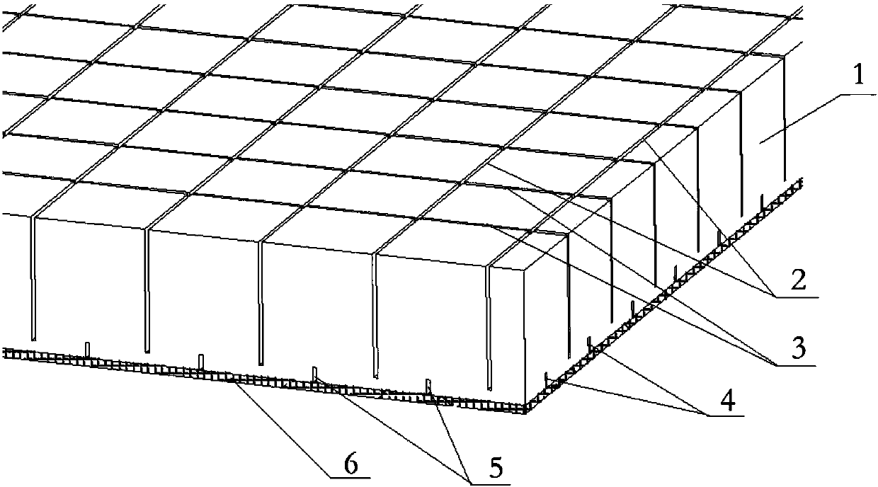
[0018] Embodiment 1, with reference to figure 1 , a blade core material of a wind power generating set, comprising a core plate 1, a main resin pouring groove is arranged on the front of the core plate, an auxiliary resin pouring groove is arranged on the back of the core plate, and a tiled resin pouring groove is arranged above the auxiliary resin pouring groove on the core plate The anti-overflow layer 6 on the back, the main resin perfusion groove includes several parallel frontal transverse slits 3 and frontal longitudinal slits 2, the frontal transverse slits 3 and the frontal longitudinal slits 2 are intersected, and the secondary resin perfusion grooves It includes a number of rear transverse grooves 4 parallel to the front transverse grooves 3 and rear longitudinal grooves 5 parallel to the front longitudinal grooves 2, and a back transverse groove 5 is provided between any adjacent two front transverse grooves 3. Cutting groove 4, is provided with a rear longitudinal ...
Embodiment 2
[0020] Embodiment 2, in the blade core material of a wind power generating set described in Embodiment 1: the front transverse groove 3 and the front longitudinal groove 2 perpendicularly intersect, and the rear transverse groove 4 and the rear longitudinal groove 5 also correspond to each other. vertical cross.
Embodiment 3
[0021] Embodiment 3, in a wind turbine blade core material described in Embodiment 1 or 2: the front transverse slots 3 and the front longitudinal slots 2 are evenly spaced, and the two adjacent front transverse slots 3 The distance a between them is set to 20-30 mm, and the distance b between two adjacent front longitudinal grooves 2 is set to 20-30 mm.
PUM
| Property | Measurement | Unit |
|---|---|---|
| thickness | aaaaa | aaaaa |
Abstract
Description
Claims
Application Information
 - R&D
- Intellectual Property
- Life Sciences
- Materials
- Tech Scout
- Unparalleled Data Quality
- Higher Quality Content
- 60% Fewer Hallucinations
Browse by: Latest US Patents, China's latest patents, Technical Efficacy Thesaurus, Application Domain, Technology Topic, Popular Technical Reports.
© 2025 PatSnap. All rights reserved.Legal|Privacy policy|Modern Slavery Act Transparency Statement|Sitemap|About US| Contact US: help@patsnap.com

