Radial drilling machine for pipe machining
A technology for radial drilling machines and pipe fittings, which is applied to metal processing equipment, metal processing machinery parts, manufacturing tools, etc. It can solve problems such as drilling deviation and reduced work efficiency, and achieves low environmental pollution, convenient operation, and remarkable sensing effect Effect
- Summary
- Abstract
- Description
- Claims
- Application Information
AI Technical Summary
Problems solved by technology
Method used
Image

Examples
Embodiment 1
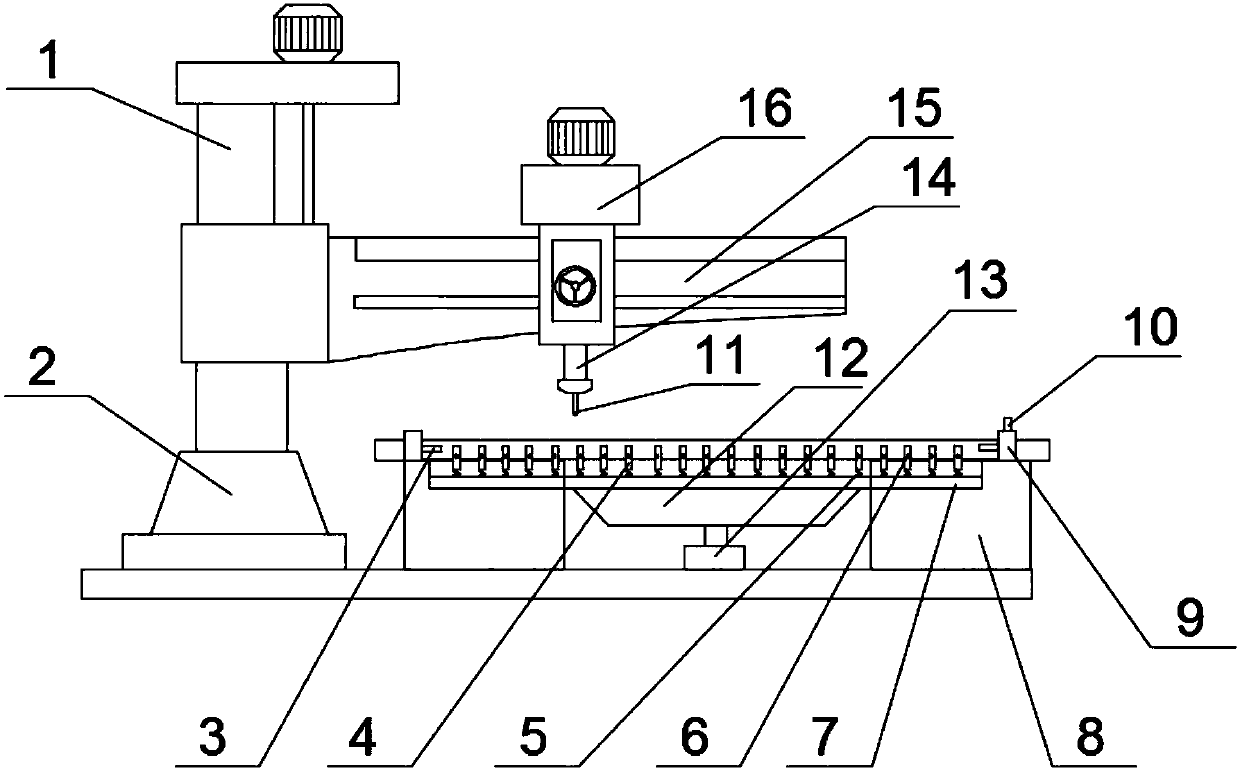
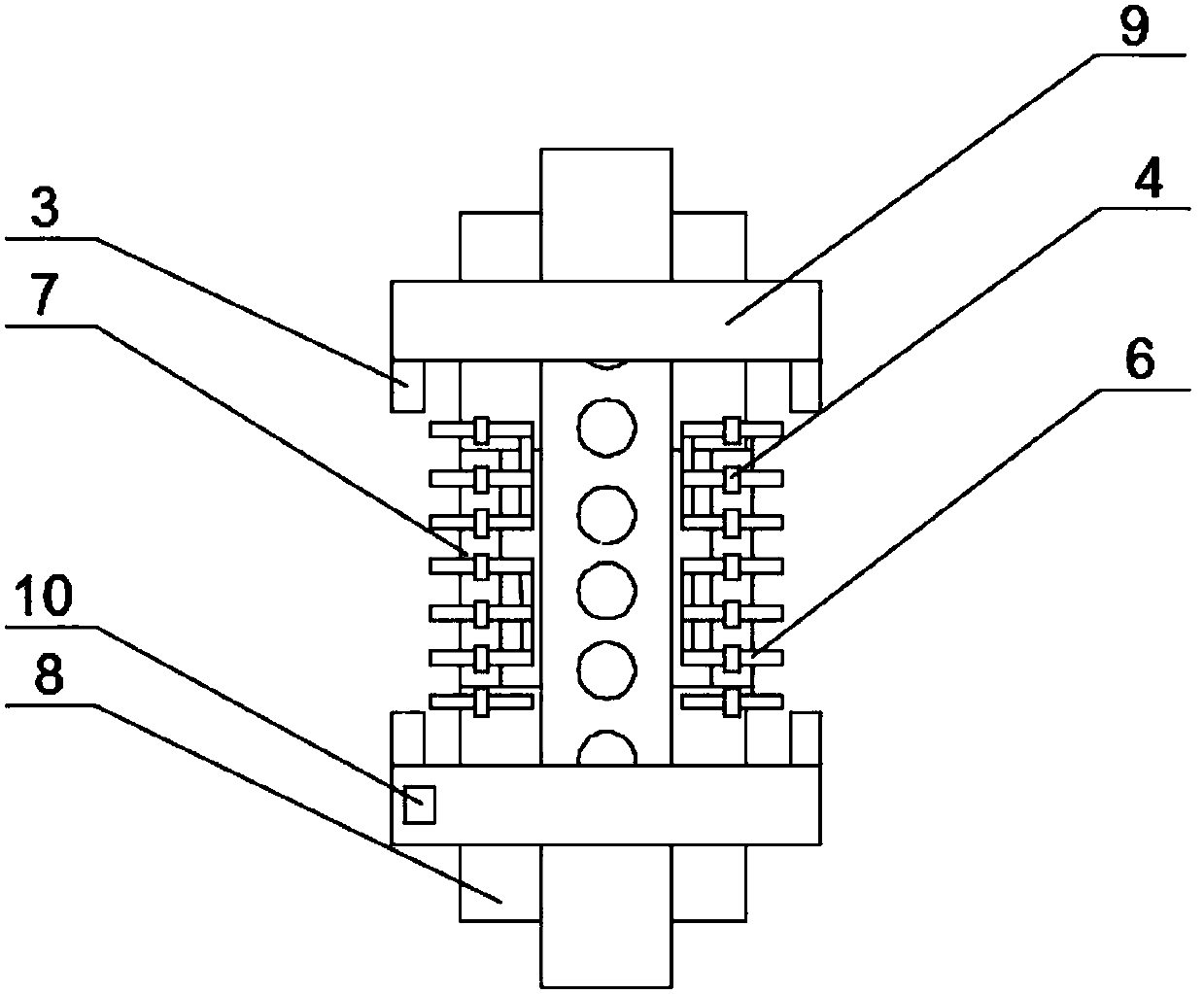
[0025] like Figure 1-3 As shown, the present embodiment provides a radial drilling machine for processing pipe fittings, including a base 2, a column 1, a rocker 15, a headstock 16, a spindle 14, a drill 11 and a workbench 8, and the base 2 is provided with a column 1 and a column 1 A rocker arm 15 is arranged on the rocker arm 15, a headstock 16 is arranged on the rocker arm 15, a main shaft 14 is arranged under the headstock 16, a drill bit 11 is arranged at the bottom of the main shaft 14, a workbench 8 is also arranged on the base 2, and the drill bit 11 is located on the workbench 8 Above, it is characterized in that: the workpiece locking blocks 9 are arranged on the workbench 8, the connecting pulleys 7 are symmetrically arranged between the workingbenches 8, and a plurality of springs 5 are arranged at intervals on the connecting pulleys 7, so Each spring 5 is provided with a strip block 4, and the workpiece locking block 9 is provided with an infrared sensor 3.
...
Embodiment 2
[0029] like Figure 1-3 As shown, the present embodiment is further optimized on the basis of embodiment 1, and the specific implementation scheme is as follows:
[0030] Both the front and rear ends of the strip block 4 are provided with induction touch rods 6 .
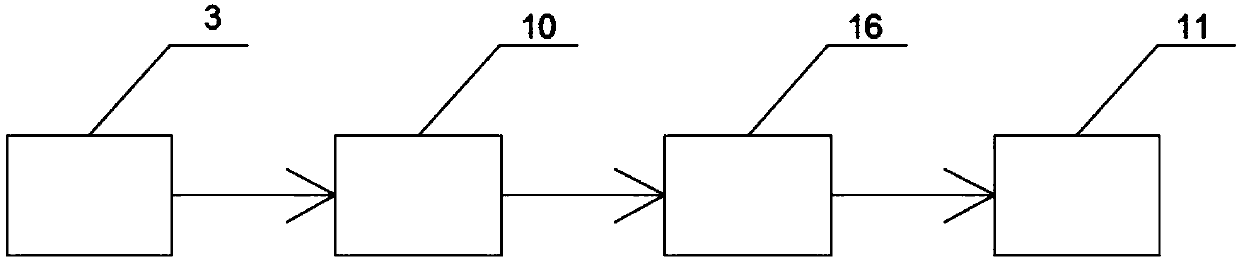
[0031] In this embodiment, when the pipe fittings are drilled, due to the vibration generated during the drilling process, the processed pipe fittings will be displaced to a certain extent. The function of the spring at the bottom of the shaped block makes the other end of the sensing touch lever touch the two infrared sensors. The infrared sensor senses the signal and sends the signal to the alarm siren. At this time, the alarm siren alarms and prompts the staff. The pipe is deflected and needs to be adjusted to avoid misalignment of the drilled hole.
Embodiment 3
[0033] like Figure 1-3 As shown, the present embodiment is further optimized on the basis of embodiment 1, and the specific implementation scheme is as follows:
[0034] The end of the inductive touch rod 6 is arranged in an arc-shaped structure that fits with the processing pipe.
[0035] In this embodiment, since the processed pipe is generally long cylindrical, the area in contact with the sensing touch rod is the point where the end of the sensing touch rod contacts the pipe, and the end of the sensing touch rod is set to fit the processed pipe The arc-shaped structure makes the pipe fitting and the sensing touch rod more fully contacted. When the pipe moves and touches the sensing touch rod, the sensing effect of the sensing touch rod will be more obvious under the action of the spring, which can be effective Prevent drilling deviation.
PUM
 Abstract
Description
Claims
Application Information
 - R&D
- Intellectual Property
- Life Sciences
- Materials
- Tech Scout
- Unparalleled Data Quality
- Higher Quality Content
- 60% Fewer Hallucinations
Browse by: Latest US Patents, China's latest patents, Technical Efficacy Thesaurus, Application Domain, Technology Topic, Popular Technical Reports.
© 2025 PatSnap. All rights reserved.Legal|Privacy policy|Modern Slavery Act Transparency Statement|Sitemap|About US| Contact US: help@patsnap.com