Circular arc surface drilling machining tool applied to numerical control machine tool

A technology of CNC machine tools and drilling devices, applied in boring/drilling, metal processing equipment, drilling/drilling equipment, etc., can solve the problems of low drilling efficiency, time-consuming, drilling deviation, etc. Hole efficiency, avoid cumbersome operations, avoid the effect of drilling deviation

Inactive Publication Date: 2019-01-01
杨祥
View PDF0 Cites 0 Cited by
  • Summary
  • Abstract
  • Description
  • Claims
  • Application Information

AI Technical Summary

Problems solved by technology

[0003] 1. The positioning of the arc-shaped plate before processing and the guidance of the tool during processing are difficult to control during drilling. It is even more difficult to drill holes on the arc surface because it is inconvenient to fix, and it is easy to cause deviations in drilling;
[0004] 2. When drilling a plate, the plate needs to be placed and fixed, and the surface seat should be drilled with the help of a drilling device. However, the traditional drilling device can only drill one plate at a time, which results in relatively low drilling efficiency. Low, affecting the production efficiency of enterprises;
[0005] 3. When drilling holes on the surface of arc-shaped plates, it needs to be clamped and fixed to avoid drilling deviation caused by its random sliding. However, it is more troublesome to process arc-shaped plates with traditional fixtures, and the same fixture can only be used for one For clamping arc-shaped plates, when multiple arc-shaped plates need to be clamped, it needs to be carried out sequentially, which is time-consuming

Method used


Image

  • Circular arc surface drilling machining tool applied to numerical control machine tool
  • Circular arc surface drilling machining tool applied to numerical control machine tool
  • Circular arc surface drilling machining tool applied to numerical control machine tool

Examples


Embodiment Construction

[0023] The following will clearly and completely describe the technical solutions in the embodiments of the present invention with reference to the accompanying drawings in the embodiments of the present invention. Obviously, the described embodiments are only some, not all, embodiments of the present invention. Based on the embodiments of the present invention, all other embodiments obtained by persons of ordinary skill in the art without making creative efforts belong to the protection scope of the present invention.

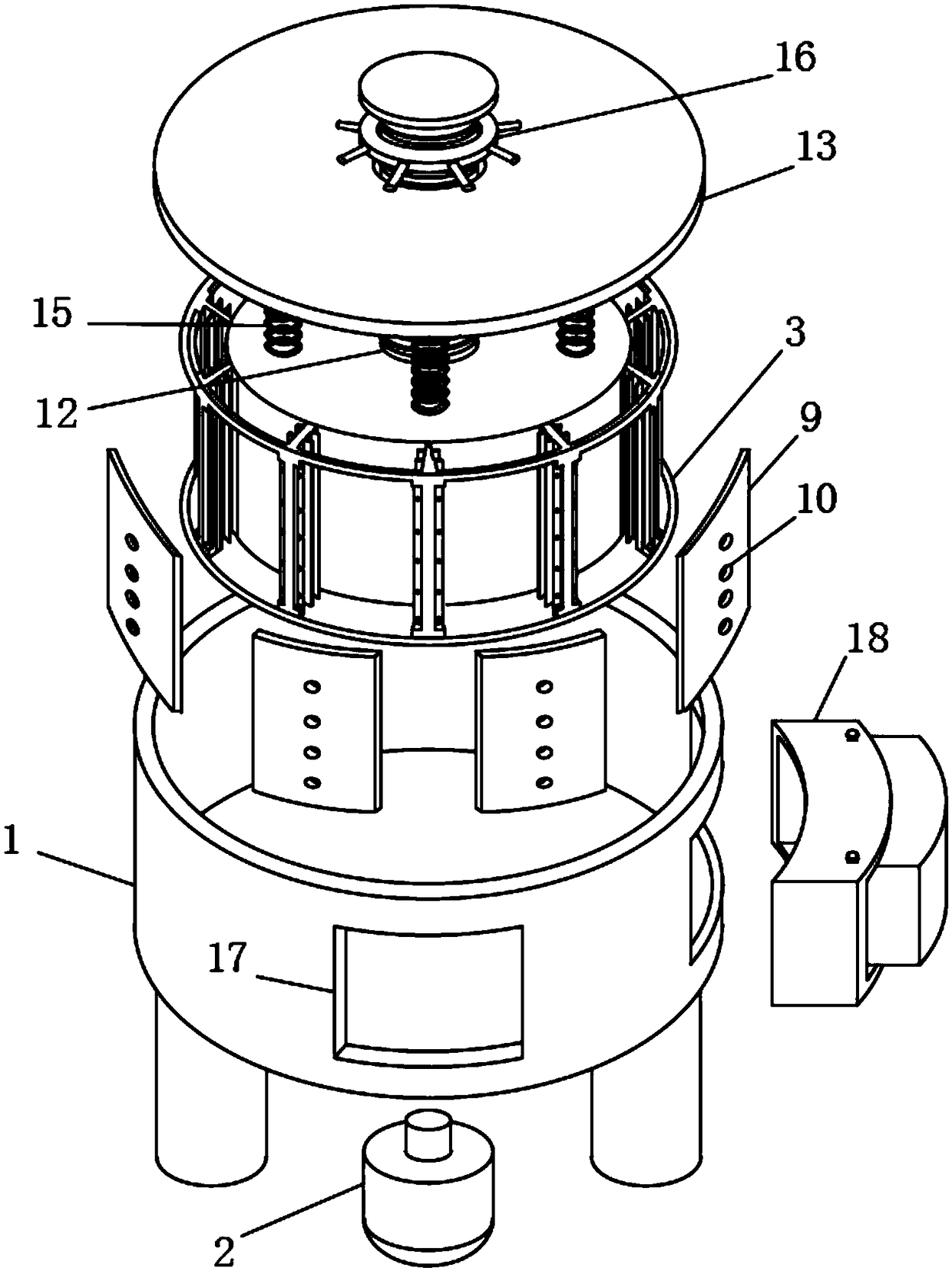
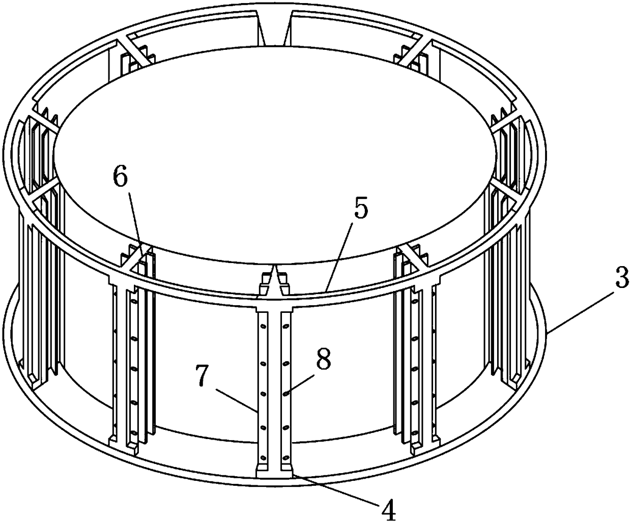
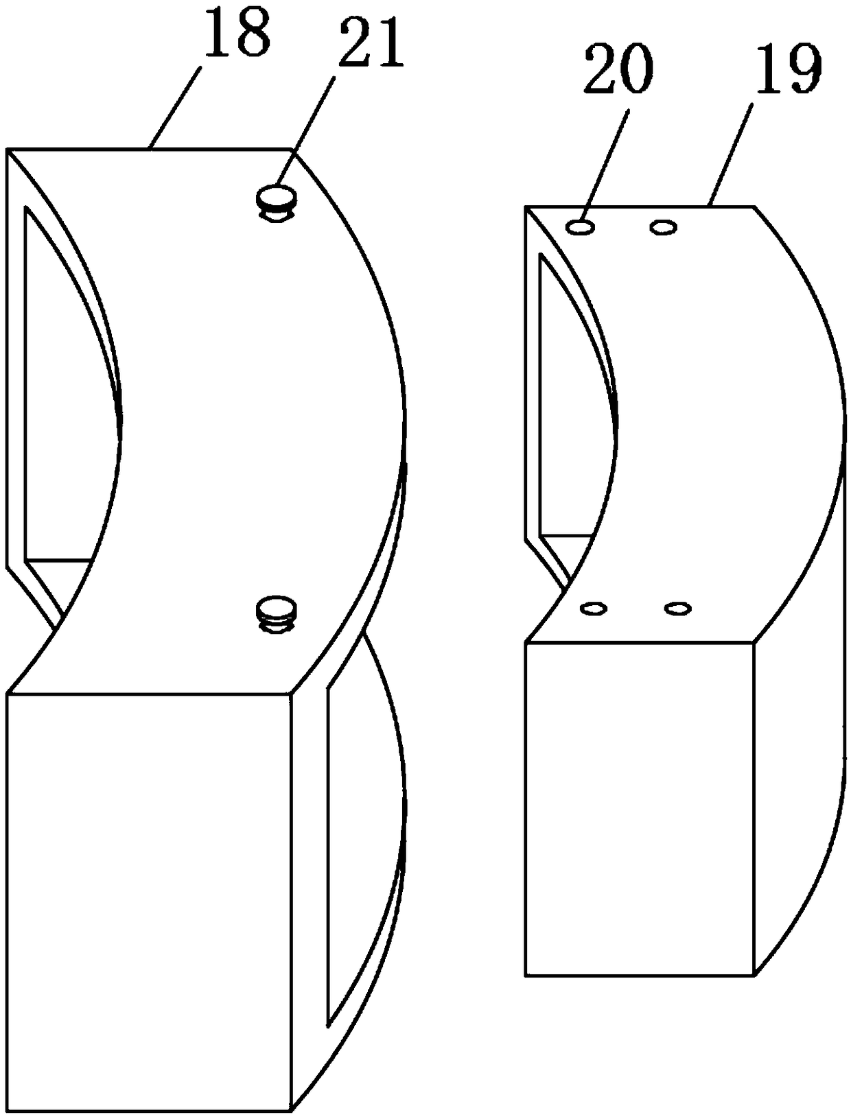
[0024] see Figure 1-5 , the present invention provides a technical solution: a circular arc surface drilling tooling applied to a CNC machine tool, comprising a support frame body 1, a placement frame 3, an auxiliary pinch plate 9, a lower pressing plate 13, and a drilling device 19, and the support frame The bottom surface of the body 1 is fixedly connected with a motor 2, the rotating shaft of the motor 2 runs through the bottom surface of the support frame...


PUM


Abstract

The invention discloses a circular arc surface drilling machining tool applied to a numerical control machine tool. The circular arc surface drilling machining tool comprises a supporting frame body,a placement frame, an auxiliary buckle plate, a lower pressing plate and a drilling device. A motor is fixedly connected to the bottom surface of the supporting frame body, and a rotating shaft of themotor penetrates through the bottom surface of the supporting frame body and is fixedly connected to the bottom surface of the placement frame. A plurality of partition plates are fixedly connected to the surface of the placement frame, connecting rings are fixedly connected between every two adjacent partition plates, and limiting sliding grooves are formed in the surfaces of the partition plates. Butting grooves are formed in the side walls of the partition plates, inserting-connecting holes are formed in the surfaces of the butting grooves, and the inserting-connecting holes connected withinserting-connecting rods arranged on the plate surface of the auxiliary buckle plate in an inserting mode. According to the circular arc surface drilling machining tool applied to the numerical control machine tool, circular arc plates are arranged and placed in a front-and-back aligned mode, drilling treatment of three circular arc plates when a drill bit drills at a time is realized, and the opening efficiency of the circular arc plates is greatly improved.

Description

technical field [0001] The invention relates to the field of mechanical technology, in particular to a circular arc surface drilling tooling applied to a numerical control machine tool. Background technique [0002] In the machinery manufacturing industry, there are many workpieces that need to be drilled by a drilling machine. In some areas, arc-shaped plates are required as supports or enclosure structures, but the surface of arc-shaped plates still has the following disadvantages when drilling holes on the surface: [0003] 1. The positioning of the arc-shaped plate before processing and the guidance of the tool during processing are difficult to control during drilling. It is even more difficult to drill holes on the arc surface because it is inconvenient to fix, and it is easy to cause deviations in drilling; [0004] 2. When drilling a plate, the plate needs to be placed and fixed, and the surface seat should be drilled with the help of a drilling device. However, the ...

Claims


Application Information

Patent Timeline
Patent Type & Authority Applications(China)
IPC IPC(8): B23B39/20
CPCB23B39/20
Inventor 杨祥
Owner 杨祥
Why Eureka
Try Eureka