Eureka AIR delivers breakthrough ideas for toughest innovation challenges, trusted by R&D personnel around the world.

Ultra-high-speed electric spindle with embedded cold air device

An ultra-high-speed, motorized spindle technology, applied in positioning devices, clamping, supporting and other directions, can solve problems such as high requirements for skilled workers, affecting drilling accuracy, affecting drilling results, etc., to achieve simple and convenient operation and ensure cooling effect. , The effect of high working stability

Pending Publication Date: 2018-02-23
GUANGDONG UNIV OF TECH
View PDF0 Cites 7 Cited by
  • Summary
  • Abstract
  • Description
  • Claims
  • Application Information

AI Technical Summary

Problems solved by technology

Therefore, this method has the following disadvantages: (1) It is necessary to manually fix and adjust the position and direction before each use. If the position and direction deviation is too large, it will seriously affect the drilling effect, especially when multiple cold air guns are used together. Complex, so higher requirements for skilled workers
(2) After experimental research, it is found that when the direction of cold air injection is at a certain angle to the axial direction of the drill, it is easy to cause radial vibration of the drill due to uneven radial force, affecting the drilling accuracy and even causing the drill to break
When the cold air jet direction is parallel to the axial direction of the drill pin, not only the cooling effect is better, but also chip removal is promoted, which is most conducive to improving the drilling quality and the life of the drill pin. However, the device used in the existing low-temperature cooling technology adjusts this Direction is quite difficult

Method used


Image

  • Ultra-high-speed electric spindle with embedded cold air device

Examples


Embodiment Construction

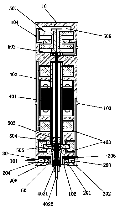
[0033] Such as figure 1 As shown, this embodiment provides an ultra-high-speed electric spindle with a built-in cold air device, which includes a spindle body, a spindle housing 10 and a cold air device. The spindle body and the cold air device are arranged inside the spindle housing 10; the side of the spindle housing 10 is provided with an inlet The air port 101, the lower end of the spindle housing 10 is vertically provided with an air outlet 102; the cold air device is sleeved on the main shaft body, the cold air device includes a hollow chamber, the bottom of the hollow chamber is provided with a heat sink 201, the upper end of the heat sink 201 on the side away from the air inlet 101 With spherical grooves, the radiating fin 201 divides the hollow chamber into a mixed gas chamber 202 and a vortex chamber 203, the upper end of the radiating fin 201 and the top of the hollow chamber form a gas guide groove 204, and the mixed gas chamber 202 communicates with the gas inlet 1...


PUM


Abstract

The invention provides an ultra-high-speed electric spindle with an embedded cold air device. The ultra-high-speed electric spindle comprises a spindle main body, a spindle shell and the cold air device. The spindle main body and the cold air device are arranged inside the spindle shell. An air inlet is formed in the side face of the spindle shell, and an air outlet is perpendicularly formed in the lower end of the spindle shell. The cold air device is sleeved with the spindle main body and comprises a hollow chamber, and a cooling fin is arranged at the bottom of the hollow chamber. The upperend of the side, away from the air inlet, of the cooling fin is provided with a spherical groove, and the cooling fin divides the hollow chamber into a mixed gas chamber body and a swirl chamber body. The upper end of the cooling fin and the top of the hollow chamber form an air guide groove, and the mixed gas chamber body communicates with the air inlet. The air guide groove is in pipeline connection with the air outlet through a cold air pipe, a hot air port is formed in the hollow chamber, and the hot air port communicates with outside air. Cold air is low temperature compressed air, low temperature CO2, supercritical CO2 or low temperature nitrogen. The cooling effect of the electric spindle is good, chip removal is facilitated, and a needle is not prone to being broken.

Description

Technical field [0001] The invention relates to a drilling device, in particular to an ultra-high-speed electric spindle embedded with a cold air device. Background technique [0002] In the PCB micro-hole processing, due to the friction between the tool and the workpiece during the drilling process, a large amount of heat will be generated. Although the chips will take away some of the heat, it is still necessary to add a cooling device for auxiliary processing. If it is not cooled, it will have many adverse effects on the quality of the processed hole, the processing accuracy and the life of the drill bit. [0003] The current main cooling methods are cutting fluid cooling and low-temperature cold air technology cooling. Cutting fluids have disadvantages such as high cost, environmental pollution, and harm to humans. The low-temperature cold air technology is widely used because of its convenient use, obvious effects, low cost, and environmental protection. [0004] However, in ...

Claims


Application Information

Patent Timeline
IPC IPC(8): B23B19/02B23Q11/12B23Q11/10B23Q3/157
CPCB23Q1/70B23Q3/157B23Q11/10B23Q11/127
Inventor 郑李娟林淡填王成勇黄欣李之源何醒荣李浩
Owner GUANGDONG UNIV OF TECH
Why Eureka
Eureka Blog
Learn More