Eureka AIR delivers breakthrough ideas for toughest innovation challenges, trusted by R&D personnel around the world.

Scale removal device for flue

A technology for flue and shaft installation, which is applied in the direction of removal of solid residue, treatment of combustion products, and combustion methods. Potential safety hazard, convenient operation, good cleaning effect

Active Publication Date: 2018-02-16
SHANDONG JINLITE PIPE IND
View PDF9 Cites 0 Cited by
  • Summary
  • Abstract
  • Description
  • Claims
  • Application Information

AI Technical Summary

Problems solved by technology

[0002] The flue is a tubular channel for the exhaust gas and smoke to be discharged. Restaurants usually have a flue. Most of the flue in the restaurant is relatively long and narrow, so as to facilitate the emission of oil fume. Since the oil in the oil fume will adhere to the inner wall of the flue, after long-term use, More oil will adhere to the inner ratio of the flue, which will lead to the gradual narrowing of the flue. Because the vertical height of the flue is large and narrow, manual cleaning can only clean the two ends of the flue, but cannot clean the middle of the flue. As a result, the middle part of the flue becomes narrower, which affects the discharge of oil fume, and because the oil fume adheres to the inner wall of the flue, the open flame in the flue can easily cause a fire, posing a safety hazard

Method used


Image

  • Scale removal device for flue
  • Scale removal device for flue
  • Scale removal device for flue

Examples


Embodiment 1

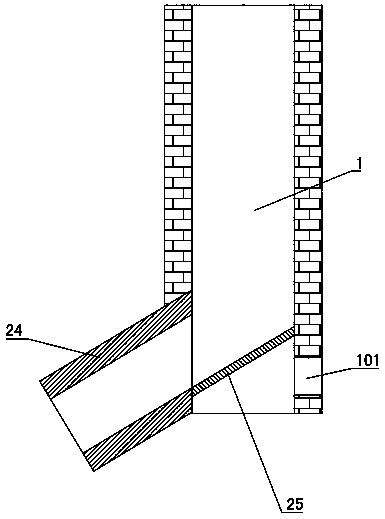
[0033] like figure 1 As shown: the bottom side of the flue 1 is provided with a smoke inlet 101, and the right side of the bottom of the flue 1 is provided with a liquid outlet pipe 24. The liquid outlet pipe 24 is inclined gradually rising from left to right, and the liquid outlet pipe The right end of 24 is aligned with the bottom of flue 1. The cleaning liquid is discharged out of the flue 1 through the liquid outlet pipe 24 . The liquid inlet end of the outlet pipe 24 is provided with a deflector 25, and the lower end of the deflector 25 is rotated and installed on the lower side of the outlet pipe 24. When the flue 1 needs to be cleaned, the upper end of the deflector 25 is turned to the right. Swing and stick to the inner wall on the right side of the flue 1, the cleaning liquid flows onto the deflector 25 and flows into the liquid outlet pipe 24 along the deflector 25, and closes the smoke inlet 101 of the flue 1, when the flue 1. During normal use, the upper side of ...

Embodiment 2

[0052] Such as Figure 8 As shown: the difference between embodiment 2 and embodiment 1 is that no installation box 6 and dry powder nozzle 11 are installed on the flue 1, and the middle part of the baffle plate 2 on the left is provided with a powder injection port, and the powder injection port is connected with a spray pipe 14 The high-pressure medium inlet of the injection pipe 14 is connected with compressed air, the low-pressure medium inlet of the injector 14 is arranged on the upper side of the injector 14, and is used to add fireproof powder, and the medium outlet of the injector 14 is connected to the powder injection port. A hopper 15 is provided on the upper side of the low-pressure medium inlet of the injector 14, and the hopper 15 has a tapered cross-sectional area gradually increasing from bottom to top, so that it is convenient to add fireproof powder. A feed valve 16 is provided between the hopper 15 and the low-pressure medium inlet of the injector 14 . Two ...

Embodiment 3

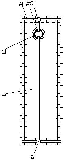
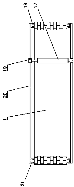
[0054] Such as Figure 9 Shown: the difference between embodiment 3 and embodiment 1 is: the diameter of the brush roller 17 is slightly larger than the width of the flue 1, and no adjustment mechanism is provided, and the two ends of the swing guide rail 20 are installed in the middle of the flue 1.


PUM


Abstract

The invention discloses a scale removal device for a flue and belongs to the technical field of flue cleaning equipment. The scale removal device is characterized in that a liquid outlet pipe (24) isconnected at the bottom of the flue (1); the liquid outlet pipe (24) is arranged on one side, opposite to a smoke inlet (101) of the flue (1); a flow guide plate (25) is further arranged at the bottomof the flue (1); the lower side of the flow guide plate (25) is rotationally mounted on the lower side of the liquid inlet end of the liquid outlet pipe (24); the upper side of the flow guide plate (25) is higher than the smoke inlet (101) all the time; and the height of the upper side of the flow guide plate (25) and the height of the lower side of the flow guide plate (25) are larger than the width of the flue (1). By the aid of the scale removal device for the flue, the ventilation effect of the flue is guaranteed, fire dangers caused by open fires in the flue are avoided, a cleaning liquid can be guided to the liquid outlet pipe by the flow guide plate and flows out of the liquid outlet pipe, meanwhile, the smoke inlet can be sealed, when the flue is used normally, the flow guide plate swings to seal the liquid outlet pipe, smoke can be prevented from overflowing the liquid outlet pipe, and the cleaning liquid can be prevented from entering the smoke inlet.

Description

technical field [0001] A flue descaling device belongs to the technical field of flue cleaning equipment. Background technique [0002] The flue is a tubular channel for the exhaust gas and smoke to be discharged. Restaurants usually have a flue. Most of the flue in the restaurant is relatively long and narrow, so as to facilitate the emission of oil fume. Since the oil in the oil fume will adhere to the inner wall of the flue, after long-term use, More oil will adhere to the inner ratio of the flue, which will lead to the gradual narrowing of the flue. Because the vertical height of the flue is large and narrow, manual cleaning can only clean the two ends of the flue, but cannot clean the middle of the flue. As a result, the middle part of the flue is getting narrower, which affects the discharge of oil fume, and because the oil fume adheres to the inner wall of the flue, the open flame in the flue can easily cause a fire, posing a safety hazard. To clean the inner wall of...

Claims


Application Information

Patent Timeline
Patent Type & Authority Applications(China)
IPC IPC(8): F23J3/02
CPCF23J3/02
Inventor 戚彬马立修李京朋国建刘玉山李涛张帅帅
Owner SHANDONG JINLITE PIPE IND
Why Eureka
Eureka Blog
Learn More