Flange guide rod pressing and connecting tool

A technology of guide rods and flanges, which is applied in the field of process equipment in the production process of automobile fuel tanks, and can solve problems such as inability to realize pressure control and displacement control, low pressure application efficiency, and high labor intensity.

Pending Publication Date: 2018-02-02
JIANGSU AOLIWEI SENSING TECH
View PDF0 Cites 0 Cited by
  • Summary
  • Abstract
  • Description
  • Claims
  • Application Information

AI Technical Summary

Problems solved by technology

[0003] However, in the prior art, the crimping of the fuel tank flange and the guide rod is mainly done manually or semi-automatically with crimping tools. Such crimping tools need to apply pressure manually, which cannot achieve pressure control and displacement control. Low efficiency, uncontrollable crimping quality, poor consistency and reliability of crimping products, and high labor intensity

Method used


Image

  • Flange guide rod pressing and connecting tool
  • Flange guide rod pressing and connecting tool
  • Flange guide rod pressing and connecting tool

Examples


Embodiment Construction

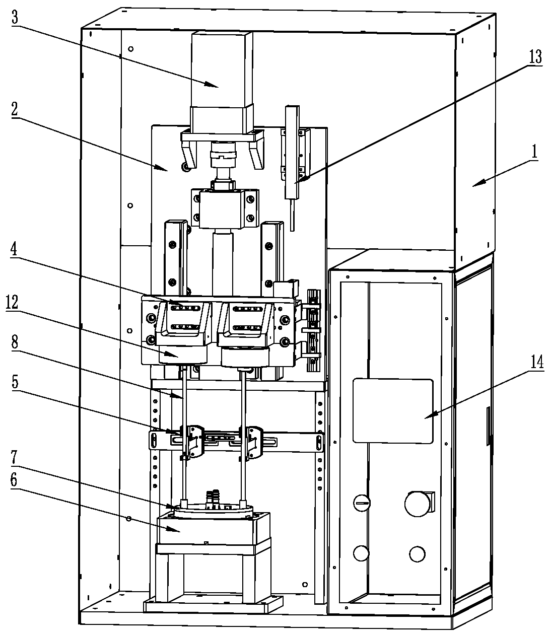
[0019] Such as figure 1 The shown flange guide rod crimping tool is fixed in the outer protective shell 1, and the outer protective shell 1 is provided with a bracket 2, and the stepping motor 3, The pressure applying device 4, the guide rod fixing device 5, and the flange fixing base 6 are arranged at the bottom of the bracket. The lower part of the front end of the housing 1 is open ( figure 1 In order to show the internal structure, the shell covering part of the front end surface is omitted to facilitate the insertion of the flange 7 and the guide rod 8. The output end of the stepping motor 3 is provided with a screw mandrel 17 . The upper end of the pressure applying device 4 is connected with the screw rod 17, the rear end of the pressure applying device 4 is slidingly connected with the longitudinal slide rail 16 arranged on the bracket 2, the guide rod fixing device 5 can keep the guide rod 8 in a vertical state, and the flange 7 is fixed When the flange is fixed on...


PUM


Abstract

The invention discloses a flange guide rod pressing and connecting tool in the field of technological equipment for the production process of automobile oil tanks. The flange guide rod pressing and connecting tool comprises a stepping motor, a pressure applying device, a guide rod fixing device and a flange fixing base which are sequentially arranged from top to bottom in the vertical direction. The stepping motor, the pressure applying device and the guide rod fixing device are fixed to a support. The output end of the stepping motor is provided with a lead screw, the upper end of the pressure applying device is connected with the lead screw, the rear end of the pressure applying device is in sliding connection with a longitudinal slide rail which is arranged on the support, and the guiderod fixing device can enable a guide rod to keep a vertical state. When a flange is fixed to the flange fixing base, the pressure applying device, the guide rod fixing device and a pressing and connecting hole of the flange are located on the same axis. The flange guide rod pressing and connecting tool is high in pressing and connecting efficiency and automation degree, easy to operate and capable of achieving precise control of displacement and displacement and pressure visualization.

Description

technical field [0001] The invention relates to a production process equipment of an automobile fuel tank, in particular to a crimping device for an automobile flange and a guide rod. Background technique [0002] Existing automobile fuel tanks include structures such as fuel tank flanges, several guide rods connected with the fuel tank flanges, pressure regulating valves, fine filters, electric fuel pumps, fuel pump brackets, and oil delivery hoses. There is a guide hole matched with the guide rod, and the guide rod is inserted into the guide hole on the side of the oil pump bracket, and the oil pump bracket can slide freely up and down along the guide rod, so that the oil pump bracket is installed on the guide rod to achieve circumferential positioning, that is, electric The fuel pump is positioned circumferentially via guide rods. [0003] However, in the prior art, the crimping of the fuel tank flange and the guide rod is mainly done manually or semi-automatically with ...

Claims


Application Information

Patent Timeline
IPC IPC(8): B23P19/02
CPCB23P19/02B23P2700/50
Inventor 蔡健高林祥陈川川刘国强陈诚
Owner JIANGSU AOLIWEI SENSING TECH
Why Eureka
Try Eureka