Bypass blocking method, device, system, and electronic device

A technology for blocking equipment and equipment, applied in the network field, can solve the problems of reduced blocking success rate, increased maintenance cost and equipment cost, long transmission distance of firewall equipment, etc., to improve the blocking success rate, meet the delay requirements, The effect of optimizing the transmission path

Active Publication Date: 2018-01-30
ALIBABA GRP HLDG LTD
View PDF5 Cites 10 Cited by
  • Summary
  • Abstract
  • Description
  • Claims
  • Application Information

AI Technical Summary

Problems solved by technology

[0006] like figure 2 As shown, for example, for a large-scale cloud service provider, multiple IDC computer rooms share the ISP network outlet line. Since the optical splitting equipment is usually fixedly deployed at the location of the ISP network outlet line, the transmission distance between the computer room where the firewall device is located and the actual service server room may be relatively long. As a result, the network transmission delay of the RESET message used for blocking cannot be guaranteed, resulting in a decrease in the blocking success rate.
[0007] for example figure 2 , when the mirrored traffic enters the bypass blocking firewall device (such as figure 2 dot-dash line), but accesses Server 1 on the A side of the IDC computer room, the bypass blocking firewall device will analyze the mirrored traffic on the line on the B side of the IDC computer room, and continue the triggered RESET message. Inject back into the access switch in the B-side computer room. Since Server 1 is in the IDC computer room A-side, the RESET message needs to bypass the core router, which increases the forwarding delay of multi-hop network devices. For example, figure 2 As shown by the dotted line in the middle, the RESET message sent by the bypass blocking firewall device is forwarded from the access switch on the B side of the IDC to the aggregation switch on the B side of the IDC, and then forwarded to the core router before being forwarded to Server 1. Wen Ru figure 2 As shown by the thick line in the middle, it is sent from the ISP network to the server 1 through the optical splitting device; therefore, it is very likely that the RESET message used for blocking reaches the target server (server 1) later than the normal service message, resulting in bypass blocking function failure
[0008] However, if in a large-scale cloud computer room deployment environment, a set of bypass blocking firewall equipment is independently deployed for each computer room, the maintenance cost and equipment cost will increase exponentially, so the traditional bypass blocking firewall equipment cannot provide Large cloud service providers provide comprehensive protection

Method used


Image

  • Bypass blocking method, device, system, and electronic device
  • Bypass blocking method, device, system, and electronic device
  • Bypass blocking method, device, system, and electronic device

Examples


Embodiment 1

[0068] Embodiment 1. A bypass blocking method, such as image 3 As shown, including steps S110-S120:

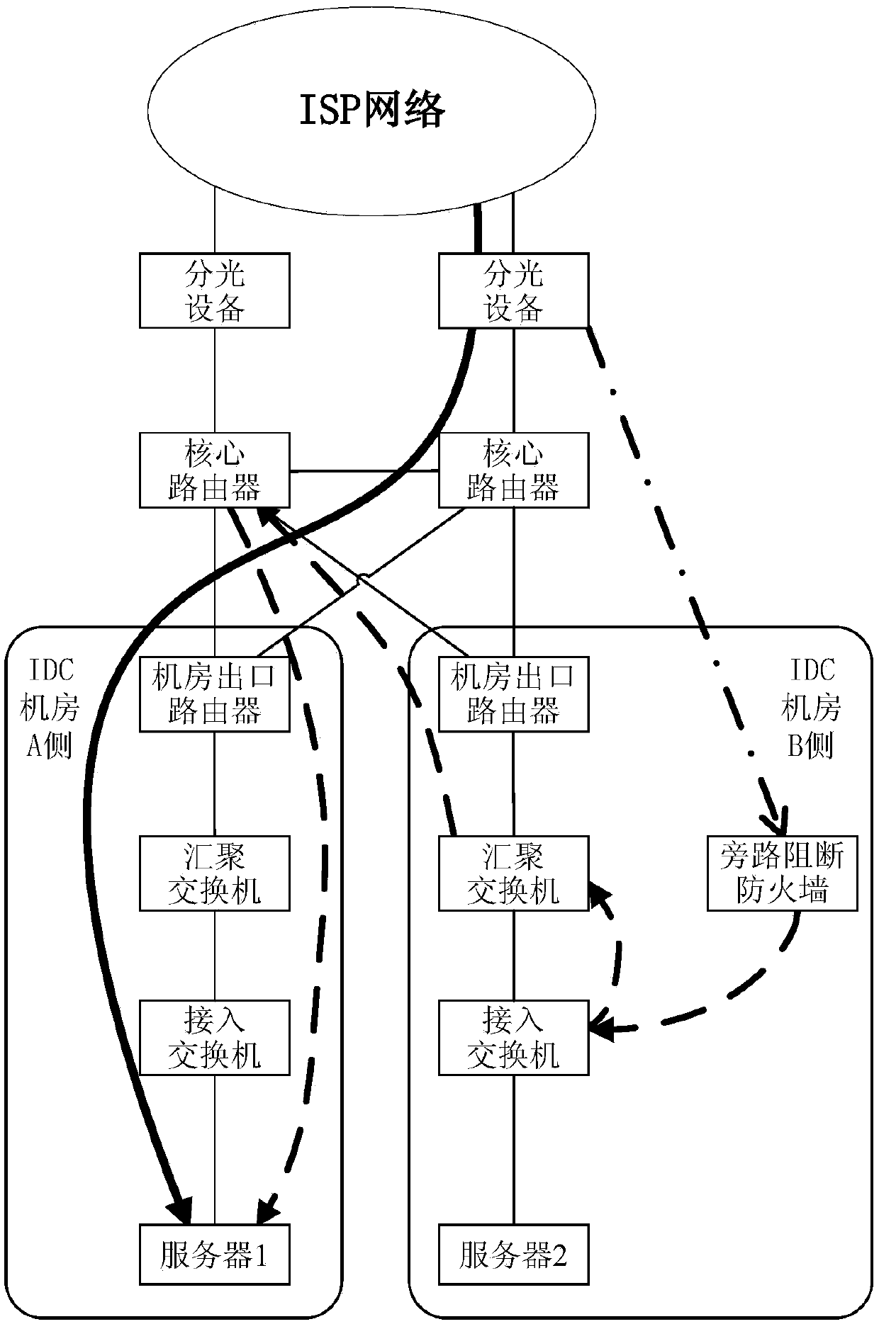
[0069] S110. The bypass blocking device receives a mirror message of a predetermined message from the distribution device; wherein the distribution device is a device for distributing downlink data of an Internet service provider (ISP) network;

[0070] S120. The bypass blocking device judges that blocking needs to be performed according to the mirror message of the predetermined message, generates a blocking message having the same destination address as the predetermined message, and sends it to multiple core routers.

[0071] In this embodiment, the bypass blocking device directly receives the mirrored message from the distribution device, which is equivalent to moving the bypass blocking device from the position close to the server in the IDC room to the entrance position of the public network (that is, the ISP network) (or It is called the access entrance position), tha...

Embodiment 2

[0107] Embodiment 2. A bypass blocking device, such as Figure 9 shown, including:

[0108] The receiving module 91 is configured to receive a mirror message of a predetermined message from a distribution device; wherein the distribution device is a device for distributing downlink data of an Internet service provider (ISP) network;

[0109] The blocking module 92 is configured to generate a blocking message with the same destination address as the predetermined message and send it to multiple core routers when judging that blocking is required according to the mirror message of the predetermined message.

[0110] In this embodiment, the receiving module 91 is a part of the device responsible for receiving mirrored messages, which may be software, hardware or a combination of both.

[0111] In this embodiment, the generation module 92 is a part in the device responsible for generating and sending the blocking message, which may be software, hardware or a combination of both. ...

Embodiment 3

[0121] Embodiment 3. A network system, comprising:

[0122] Distribution equipment, used to distribute the downlink data of the ISP network of the Internet service provider;

[0123] Multiple core routers for forwarding received downlink data;

[0124] Bypass blocking device;

[0125] The bypass blocking device is used to receive the mirrored message of the predetermined message from the distribution device; when it is judged that blocking needs to be performed according to the mirrored message of the predetermined message, generate a reset with the same destination address as the predetermined message The message is sent to the multiple core routers.

[0126] The network system in this embodiment can be regarded as, but not limited to, a cloud service data center; or in other words, it can be regarded as including Figure 5-8 In addition to the ISP network part of the system.

[0127] In this embodiment, the bypass blocking device can be regarded as the bypass blocking de...


PUM


Abstract

The invention provides a bypass blocking method, device, system, and electronic device. The bypass blocking method comprises the steps that a bypass blocking device receives a mirror image report of predetermined message from a distributing device, wherein the distributing device is used for distributing the downstream data of an Internet service provider (ISP network); the bypass blocking devicedetermines whether blocking is required or not based on the mirror image report of the predetermined message, and generates a blocking report having the same destination address as the predetermined message, and sends the blocking report to a plurality of core routers. The invention is advantageous in that the disposition difficulty and cost of bypass blocking can be reduced, and the time-delay demand of the bypass blocking can be guaranteed to a certain degree.

Description

technical field [0001] The present invention relates to the network field, in particular to a bypass blocking method, device, system and electronic equipment. Background technique [0002] Bypass blocking technology uses bypass interception to obtain all data packets passing through the firewall device, restores and analyzes the protocol content to identify illegal information in the restored content, and blocks accordingly. [0003] HTTP (HyperText Transfer Protocol, hypertext transfer protocol) bypass blocking refers to analyzing the REQUEST (request) message using HTTP, blocking the fast and accurate calculation and matching of the firewall device through the bypass, and generating a fake RESET that blocks the use The (reset) message is sent to the server to stop the HTTP session transmission that the bypass analysis thinks needs to be stopped, and do corresponding interruption and prevention processing for the access and transmission of suspicious content. However, the ...

Claims


Application Information

Patent Timeline
Patent Type & Authority Applications(China)
IPC IPC(8): H04L29/06H04L12/46H04L12/741H04L12/761H04L45/16H04L45/74
Inventor 席永青张岳安龙送张柱
Owner ALIBABA GRP HLDG LTD
Why Eureka
Try Eureka