Part for clock movement

A clock movement and core technology, which is applied in the fields of non-magnetic pivoting mandrels, fork shafts, escapement pinion shafts, and pendulum shafts, can solve the problems of expensive alloys, high cost, and difficulty in machining chips.

Pending Publication Date: 2018-01-26
NIVAROX FAR
View PDF11 Cites 2 Cited by
  • Summary
  • Abstract
  • Description
  • Claims
  • Application Information

AI Technical Summary

Problems solved by technology

However, these alloys may show difficulty in chip removal machining
Furthermore, these alloys are relatively expensive due to the high cost of nickel and cobalt

Method used


Image

  • Part for clock movement
  • Part for clock movement

Examples


Embodiment Construction

[0034] In this specification, the term "non-magnetic" refers to a paramagnetic or diamagnetic or antiferromagnetic material having a magnetic permeability lower than or equal to 1.01.

[0035] A copper alloy is an alloy comprising at least 50% copper by weight.

[0036] The present invention relates to a component for a timepiece movement, and in particular to a non-magnetic pivoting arbor for a mechanical timepiece movement.

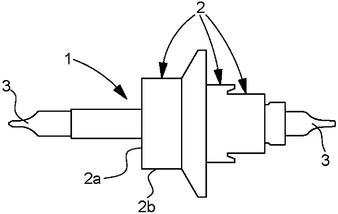
[0037] The invention will be described below with reference to the application of a non-magnetic balance shaft 1 . Of course, other types of timepiece pivot arbors are also conceivable, such as a timepiece wheel set arbor, typically an escapement pinion or a fork. Such a component has a body with a diameter of preferably less than 2 mm and a pivot with a diameter of preferably less than 0.2 mm, with an accuracy of a few micrometers.

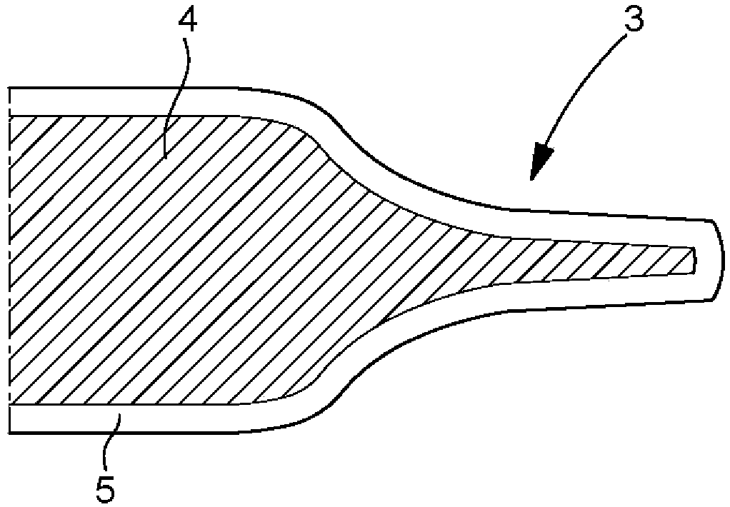
[0038] refer to figure 1 , which shows a pendulum 1 according to the invention comprising a plurality of sections 2 o...


PUM

PropertyMeasurementUnit
hardnessaaaaaaaaaa
hardnessaaaaaaaaaa

Abstract

The invention relates to a pivot axis having at least one pivot (3), which is made of metal, at at least one of its ends. The metal is a non-magnetic copper alloy in order to limit its sensitivity tomagnetic fields and at least the outer surface (5) of one of the two pivots (3) is hardened in depth relative to the rest of the axis to a predetermined depth in order to harden the pivot or pivots (3). The invention relates to the field of watch movements.

Description

technical field [0001] The present invention relates to a component for a timepiece movement, and in particular to a non-magnetic pivoting arbor for a mechanical timepiece movement, and more particularly to a non-magnetic balance, fork and escapement pinion. Background technique [0002] Manufacturing pivoting arbors for timepieces involves performing a bar turning operation on a hardenable steel bar to define various working surfaces (bearing surfaces, shoulders, pivots, etc.) and then subjecting the bar turned arbor to heat treatment , said heat treatment comprising at least one hardening operation to increase the hardness of the mandrel and one or more tempering operations to increase the toughness of the mandrel. The heat treatment operation is followed by an operation of rolling the pivot of the mandrel, which includes polishing the pivot to the required dimensions. The stiffness and roughness of the pivot portion are further improved during the rolling operation. It ...

Claims


Application Information

Patent Timeline
Patent Type & Authority Applications(China)
IPC IPC(8): G04B13/02G04B43/00
CPCG04B13/02G04B17/32G04B15/14G04B1/16G04B43/007G04D3/0069G04B1/00
Inventor C·沙邦A·弗辛格M·韦拉尔多
Owner NIVAROX FAR
Why Eureka
Try Eureka