Friction clutch device

A technology of friction clutches and components, applied in the direction of friction clutches, clutches, mechanically driven clutches, etc., which can solve the problems that the disc spring cannot be erected significantly and the stroke is short

Active Publication Date: 2018-03-27
SCHAEFFLER TECH AG & CO KG
View PDF15 Cites 0 Cited by
  • Summary
  • Abstract
  • Description
  • Claims
  • Application Information

AI Technical Summary

Problems solved by technology

In the new state of the friction linings arranged between the pressure plate and the counter-pressure plate for the frictional transmission of torque to the clutch disc, the stroke of the pressure plate for closing the friction clutch is still very short, so that the disc springs cannot stand up significantly

Method used


Image

  • Friction clutch device
  • Friction clutch device
  • Friction clutch device

Examples


Embodiment Construction

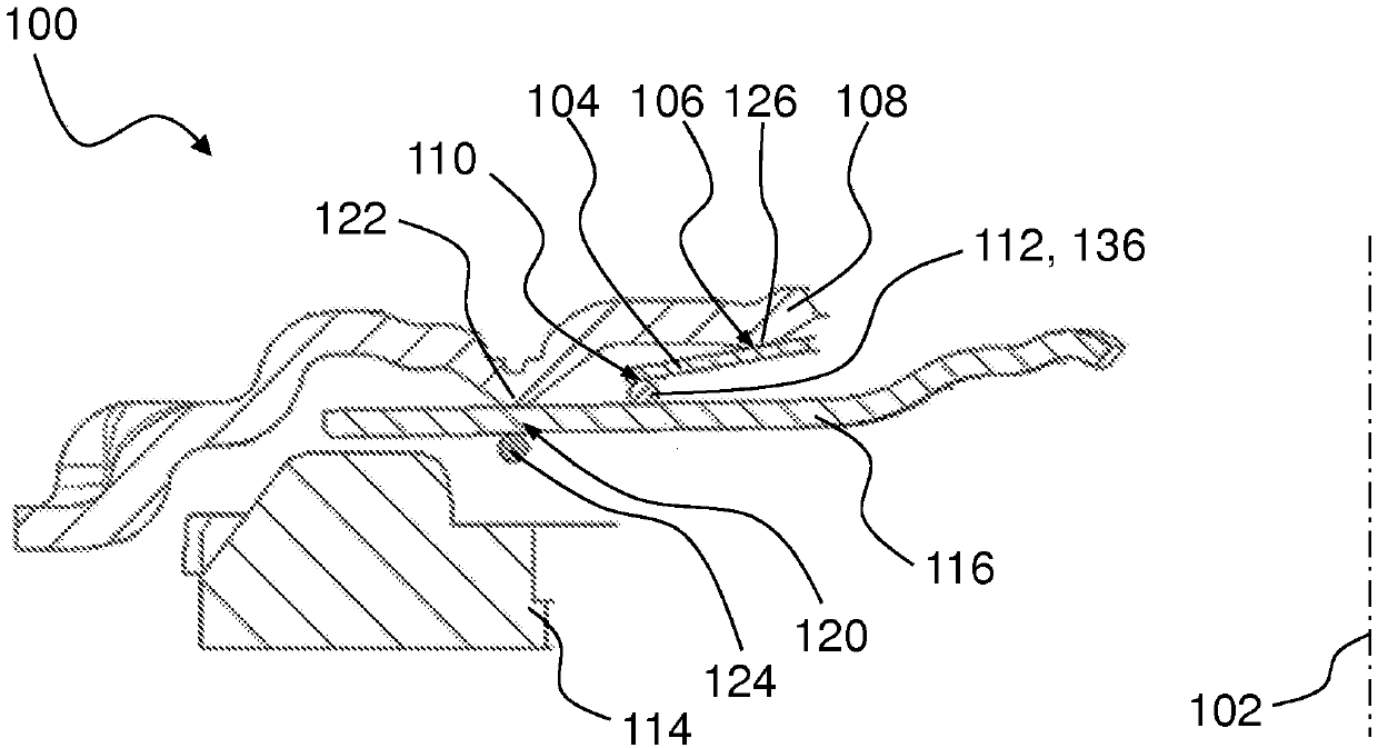
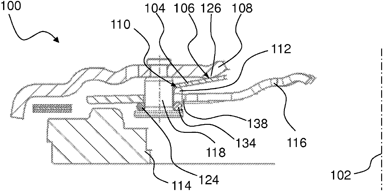
[0036] figure 1 and figure 2 Partially shows a clutch 100 rotatable about an axis of rotation 102 , which has a servo spring 104 which is supported on a housing 108 with a first support radius 106 and is supported with a second support radius 110 in a configuration configured as On the support ring of the first wire ring 112. The directional designations used below, axial, radial, circumferential and circumferential directions are all relative to the axis of rotation 102 .

[0037] Clutch 100 is a friction clutch. Clutch 100 is a single disc dry clutch. The clutch 100 can be arranged between the internal combustion engine and the transmission in the drive train of the motor vehicle. A torsional vibration damper, in particular a dual mass flywheel, can be arranged between the internal combustion engine and the clutch 100 . Clutch 100 has an input portion and an output portion. The input part comprises: a housing 108 , a pressing plate fixedly connected to the housing 108...


PUM


Abstract

A friction clutch device (100), in particular for a drivetrain of a motor vehicle powered by an internal combustion engine, comprises an axis of rotation (102); a housing (108); at least one pressureplate (114) which, for an actuation, is displaceable relative to the housing (108) in a direction of extent of the axis of rotation (102) between an engaged actuation position and a disengaged actuation position; a first spring (116) for exerting load on the at least one pressure plate (114); at least one spacer element (118) for the mounting of the first spring (116) on the housing (108); and a second spring (104) for reducing an actuation force, arranged between the housing (108) and the first spring (116) and supported by way of a first support radius (106) on the housing (108) and by way of a second support radius (110) on a support ring (112). The support ring, in the disengaged actuation position of the pressure plate (114), is supported, in the direction of extent of the axis of rotation (102), on the at least one spacer element (118) in order to structurally and / or functionally improve the friction clutch device (100).

Description

technical field [0001] The invention relates to a friction clutch device, in particular for a drive train of a motor vehicle driven by an internal combustion engine, having: an axis of rotation; a housing; at least one pressure plate for switching between an engaged actuating position and a disengaged actuating position manipulation can be displaced relative to the housing in the direction of extension of the axis of rotation; a first spring for loading the at least one pressing plate; at least one spacer element for supporting the first spring on the on the casing; and a second spring for reducing the operating force, which is arranged between the casing and the first spring and supported on the casing with a first support radius. Background technique [0002] DE 10 2012 218 876 A1 discloses an actuating device for a friction clutch, comprising: a clutch cover; a disk spring arranged directly or indirectly on the clutch cover and pivotably mounted about a particularly annul...

Claims


Application Information

Patent Timeline
Patent Type & Authority Applications(China)
IPC IPC(8): F16D13/58
CPCF16D13/585F16D13/71F16D2125/582
Inventor M·凯勒S·霍伊贝格尔
Owner SCHAEFFLER TECH AG & CO KG
Why Eureka
Try Eureka