
Rotary cutting tool with replaceable tool bit and rotary cutting method and tool bit mounting method thereof

A technology of rotating cutting tools and tool heads, which is used in milling cutters, manufacturing tools, metal processing equipment, etc. to achieve reliable processing, improve the strength of the tool bar, and reduce torsional deformation.

Active Publication Date: 2018-01-26
ZHEJIANG XINXING TOOLS CO LTD
View PDF7 Cites 5 Cited by
  • Summary
  • Abstract
  • Description
  • Claims
  • Application Information

AI Technical Summary

Problems solved by technology

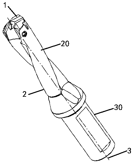
[0004] The purpose of the present invention is to overcome the above-mentioned deficiencies in the prior art, and to provide a rotary cutting tool with a replaceable cutter head, its rotary cutting method, and a cutter head installation method. It is detachably connected with the cutter bar. When the cutter head reaches the service life, it only needs to replace the cutter head. There is no need to replace the cutter as a whole. The connection between the cutter head and the cutter rod adopts V-shaped surface positioning to effectively position and fix the cutter head On the tool bar, it is not easy to deviate during the drilling process. The different helical angles of the chip flute are designed to meet the chip removal effect while reducing the depth of the chip flute and improving the strength of the tool bar. The design of the cooling guide groove can precisely control the cooling The output direction of the liquid achieves uniform and thorough cooling, avoiding the blockage of the cooling port, the installation and disassembly of the cutter head is simple, and the use cost is reduced

Method used


Image

  • Rotary cutting tool with replaceable tool bit and rotary cutting method and tool bit mounting method thereof
  • Rotary cutting tool with replaceable tool bit and rotary cutting method and tool bit mounting method thereof
  • Rotary cutting tool with replaceable tool bit and rotary cutting method and tool bit mounting method thereof

Examples


Embodiment Construction

[0031] The present invention will be further described in detail below in conjunction with the accompanying drawings and examples. The following examples are explanations of the present invention and the present invention is not limited to the following examples.

[0032] Example.

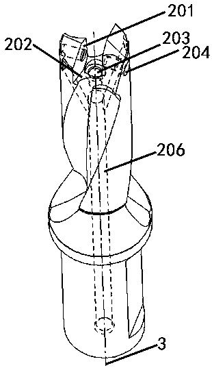
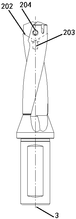
[0033] see Figure 1 to Figure 10, a rotary cutting tool with a replaceable cutter head, including a cutter head 1 and a cutter bar 2, the cutter head 1 is detachably connected to the cutter bar 2, the cutter head 1 and the cutter bar 2 have a common axis 3, and the tool bar 2 Along the axis 3 there is a blade 20 and a shank 30 , the blade 20 being connected to the cutting head 1 .

[0034] The cutter head 1 includes a cutting edge 10, a chisel edge chip surface 15, a contact surface 12, a cutter head screw hole 11, a circumferential cutting edge 16, a convex V-shaped positioning surface 13, and a central positioning cylinder 14; the cutter head 1 is a centrally symmetrical structure , the cutter...


PUM


Abstract

The invention relates to a rotary cutting tool with a replaceable tool bit and a rotary cutting method and a tool bit mounting method thereof and belongs to the field of hole processing in machining industry. At present, a twist drill used for drilling is of an integrated structure, and the tool bit reaching the service life needs to be replaced integrally, so that the cost is relatively high. Ina drilling tool with the replaceable tool, as the tool bit is subjected to relatively great radial and axial actions in the drilling hole, the condition of no fine drilling as the tool bit shifts radially at the connection is avoided. According to the replaceable structure of the tool bit, the drilling tool at the connection of the tool bit is relatively weak, and the drilling tool matrix is weaker due to a design of a chip removal chute. According to the rotary cutting tool with the replaceable tool bit provided by the invention, the tool bit is detachably connected to a cutter bar and the connection of the tool bit and the cutter bar is a V-shaped locating surface, so that the rotary cutting tool is good in tool bit positioning and fixing effect, and is unlikely to shift. The strength ofthe cutter bar is improved due to different spiral angles of the chip removal chute; the cooling effect is enhanced by a design of a cooling guide slot, and the tool bit is simple to mount and detach.

Description

technical field [0001] The invention relates to a rotary cutting tool with a replaceable cutter head, a rotary cutting method and a cutter head installation method, belonging to the field of hole processing in the mechanical processing industry. Background technique [0002] At present, the twist drill used for drilling has an integrated structure, and the overall drilling tool needs to be replaced when the cutter head reaches the service life, and the cost is relatively high, such as the Chinese patent application number 201310750248.5. [0003] In the drilling tool with replaceable cutter head, during the drilling process, due to the large radial and axial force on the cutter head, the radial displacement of the cutter head at the joint will cause the drilling to be imprecise. The replaceable structure of the head makes the drill bit more fragile at the joint of the cutter head, and the design of the flute makes the base of the drill tool more fragile, such as the Chinese ...

Claims


Application Information

Patent Timeline
Patent Type & Authority Applications(China)
IPC IPC(8): B23C5/10B23C5/22B23C5/28
CPCY02P70/10
Inventor 朱冬伟董辉
Owner ZHEJIANG XINXING TOOLS CO LTD
Learn More