E-band wide beam antenna and antenna device

A wide-beam antenna and frequency band technology, applied in the field of microwave antennas, can solve the problems of point-to-point communication alignment angle deviation, high antenna gain and narrow half power, and small antenna half power angle, etc., and achieves low return loss, low cost, and gain. big effect

Active Publication Date: 2018-01-23
TONGYU COMM INC
View PDF7 Cites 4 Cited by
  • Summary
  • Abstract
  • Description
  • Claims
  • Application Information

AI Technical Summary

Problems solved by technology

[0002] The microwave antenna is an important part of the microwave relay communication system. The E-band frequency band (71GHz-86GHz) antenna has a very wide bandwidth, the relative bandwidth is 19.1%, and the transmission efficiency is high. It is often used for long-distance big data transmission. Conventional E-band The parabolic diameter of the band antenna is 0.3m and 0.6m. At the same time, because of the high frequency, the half-power angle of the antenna with the same aperture is smaller, so the antenna has the characteristics of high gain and narrow half-power, weak anti-shaking ability, and difficult for workers to align when installing. Even installing an antenna can take a day
In practical applications, the antenna is directly attacked by natural storms, ice and snow, etc., shaking or ice loads will cause deviations in the alignment angle of point-to-point communications. For the E-band frequency band with a small half-power angle, the alignment angle is slightly deviated, resulting in There is a high probability of communication interruption

Method used


Image

  • E-band wide beam antenna and antenna device
  • E-band wide beam antenna and antenna device
  • E-band wide beam antenna and antenna device

Examples


Embodiment Construction

[0035] The following will clearly and completely describe the technical solutions in the embodiments of the present invention with reference to the accompanying drawings in the embodiments of the present invention. Obviously, the described embodiments are only some, not all, embodiments of the present invention. Based on the embodiments of the present invention, all other embodiments obtained by persons of ordinary skill in the art without making creative efforts belong to the protection scope of the present invention.

[0036] Hereinafter, specific embodiments of the E-band wide beam antenna and the antenna device according to the present invention will be described by using the embodiment of the E-band wide beam antenna device.

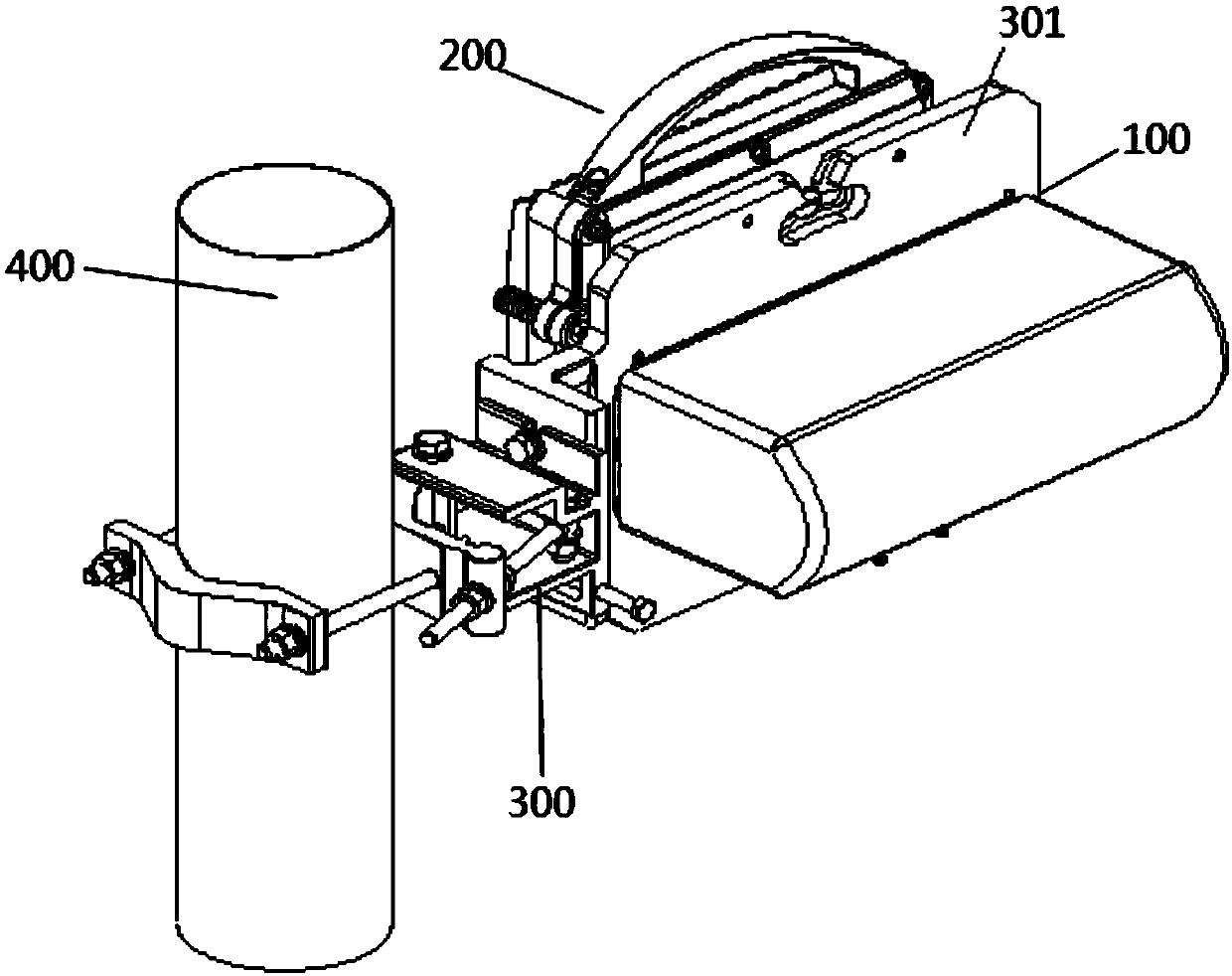
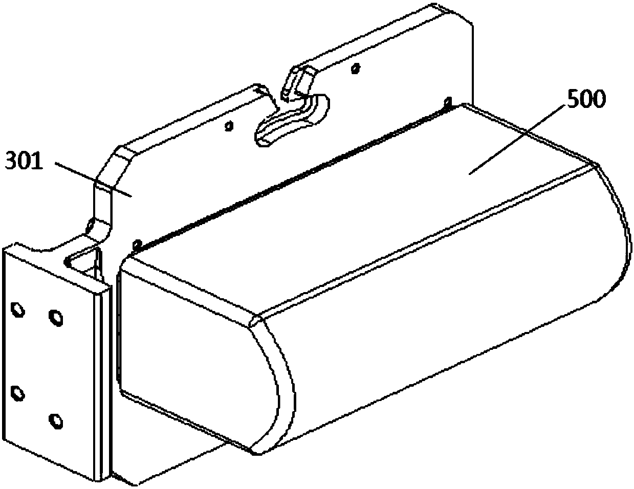
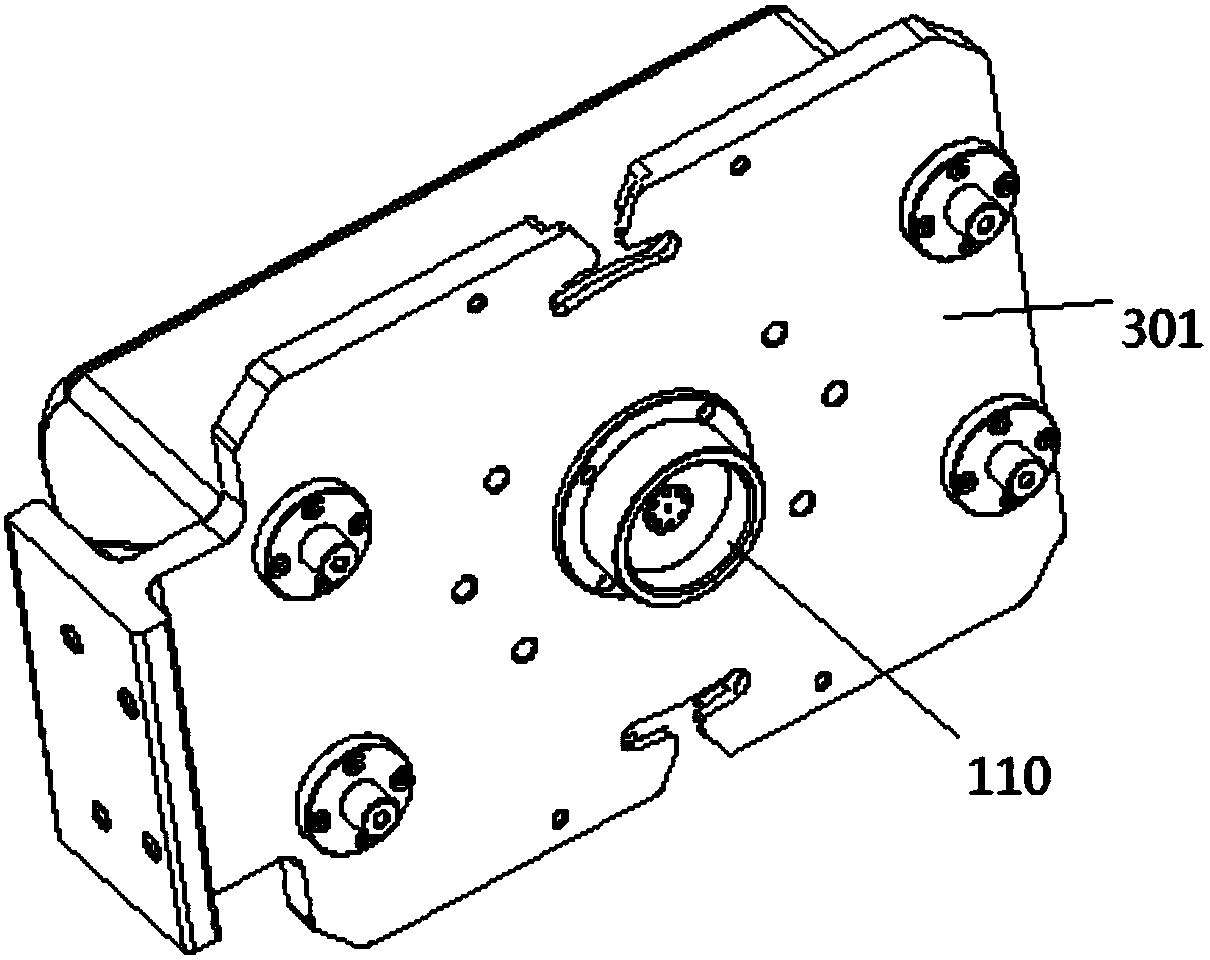
[0037] see figure 1 , an embodiment of the E-band frequency band wide beam antenna device of the present invention, which includes an E-band frequency band wide beam antenna 100, and an exposed unit 200, the exposed unit 200 is installed on the back...


PUM


Abstract

The invention discloses an E-band wide beam antenna, comprising a feed source assembly, a medium filling block and a reflection surface. The feed source assembly comprises a waveguide transmission cavity and a loudspeaker feed source. The loudspeaker feed source is connected with the waveguide transmission cavity. The medium filling block is nested in a loudspeaker opening of the loudspeaker feedsource. The reflection surface receives electromagnetic waves radiated by the loudspeaker feed source, thereby carrying out reflection to transmit the electromagnetic waves externally. The loudspeakerfeed source is located at a focus position of the reflection surface. An E-band wide beam antenna device provided by the invention comprises the E-band wide beam antenna and an exposure unit which are fixed on a lifting rod through a hanger. According to the E-band wide beam antenna and the antenna device, a wide half-power angle is achieved, so shake influence can be effectively resisted; the performance is excellent; a standing-wave ratio is low; the return loss is low; the gain is high; an antenna size is relatively small and compact; a structure is reliable; a windward area is reduced; the wind resistance ability is relatively high; the weather resistance ability is excellent; the cost is low; the electrical performance can be ensured; and the antenna can be prevented from being influenced by a complex and hostile environment.

Description

【Technical field】 [0001] The invention relates to the technical field of microwave antennas, and is particularly suitable for microwave antennas in the E-band frequency range. 【Background technique】 [0002] The microwave antenna is an important part of the microwave relay communication system. The E-band frequency band (71GHz-86GHz) antenna has a very wide bandwidth, the relative bandwidth is 19.1%, and the transmission efficiency is high. It is often used for long-distance big data transmission. Conventional E-band The parabolic diameter of the band antenna is 0.3m and 0.6m. At the same time, because of the high frequency, the half-power angle of the antenna with the same aperture is smaller, so the antenna has the characteristics of high gain and narrow half-power, weak anti-shaking ability, and difficult for workers to align when installing. Even installing an antenna can take a day. In practical applications, the antenna is directly attacked by natural storms, ice and ...

Claims


Application Information

Patent Timeline
Patent Type & Authority Applications(China)
IPC IPC(8): H01Q1/36H01Q5/20H01Q1/50H01Q15/14H01Q21/00
CPCY02D30/70
Inventor 李健林陈鹏羽吴中林李骁男张锐明熊国辉黄均顺麦国亮
Owner TONGYU COMM INC
Why Eureka
Try Eureka