
Drill jumbo test equipment

A technology of rock drilling rigs and test equipment, which is applied to the testing of machines/structural components, measuring devices, instruments, etc., which can solve the problems of kinetic energy consumption, poor reliability, and easy damage, so as to avoid heating problems, ensure cleanliness, The effect of reducing the source of failure

Pending Publication Date: 2018-01-23
CHINA RAILWAY CONSTR HEAVY IND
View PDF0 Cites 3 Cited by
  • Summary
  • Abstract
  • Description
  • Claims
  • Application Information

AI Technical Summary

Problems solved by technology

Because the drill bit of the rock drill directly acts on the piston rod of the thrust resistance cylinder, when the drill bit of the rock drill is pressed against the piston rod of the thrust resistance cylinder for impact and rotary motion, the power is transmitted to the thrust resistance cylinder, so that the piston rod moves circumferentially in the cylinder barrel at the same time. Rotary and axial linear movement, the seal on the piston is easily damaged under the simultaneous action of two directions of movement, and the reliability is poor
In addition, since the rotation relies on the friction of the brake to consume kinetic energy, the problem of heat dissipation needs to be considered for a long time
In addition, due to the need to connect the rock drilling rig propulsion beam and the rock drilling machine pipeline to the test bench during the test, it takes a long time to complete the test

Method used


Image

  • Drill jumbo test equipment
  • Drill jumbo test equipment
  • Drill jumbo test equipment

Examples


Embodiment Construction

[0022] The core of the present invention is to provide a rock drilling jumbo test equipment, which is low cost, reusable, convenient to operate and can truly simulate various rock drilling conditions.

[0023] In order to enable those skilled in the art to better understand the solution of the present invention, the present invention will be further described in detail below in conjunction with the accompanying drawings and specific embodiments.

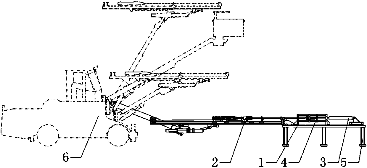
[0024] Please refer to Figure 1 to Figure 4 , figure 1 It is an installation schematic diagram of a specific embodiment of the rock drilling rig test equipment provided by the present invention; figure 2 It is a schematic front view of a specific embodiment of the rock drilling rig test equipment provided by the present invention; image 3 It is a schematic top view of a specific embodiment of the rock drilling rig test equipment provided by the present invention; Figure 4 It is a hydraulic principle diagram of a specific embod...


PUM


Abstract

The invention discloses drill jumbo test equipment, which comprises a test stand, a rotary load simulation device, a propulsion load simulation device and a sliding guide device, wherein the rotary load simulation device, the propulsion load simulation device and the sliding guide device are arranged on the test stand. The rotary load simulation device comprises a rotary transmission mechanism used for transmitting the drill pipe rotation of a drill jumbo, and a rotary load power mechanism used for providing a simulated rotary load. The propulsion load simulation device comprises a rock simulation block configured to abut against the drill bit of the drill jumbo, a propulsion transmission mechanism used for transmitting the linear motion of the drill bit, and a propulsion load power mechanism used for providing a simulated proportion load. The rock simulation block can synchronously rotate together with the drill bit. The sliding guide device comprises a push block configured to abut against the proportion beam of the drill jumbo, and a supporting and guiding mechanism used for supporting and guiding the movement of the propulsion transmission mechanism. In this way, the heating problem caused by the relative friction motion between the drill bit and the rock simulation block can be avoided. Meanwhile, the abrasion of the equipment, generated when two motions are simultaneouslyprocessed by the equipment, can be avoided.

Description

technical field [0001] The invention relates to the field of rock drilling equipment, in particular to a rock drilling rig test equipment. Background technique [0002] Although the use of shield machines for tunnel construction has become more and more popular in recent years, the proportion of tunnel construction at home and abroad is still very large, especially for some tunnels whose geological conditions are not suitable for shield tunneling. It has become a tunnel construction method commonly used by various construction units. Traditional manual pneumatic rock drilling is labor-intensive and the working environment is harsh, which no longer meets the social requirements for environmental protection and operating comfort of rock drill products. Due to its many advantages such as high construction efficiency, high degree of automation, low labor intensity, and good environmental protection, rock drilling rigs have become important equipment for modern drilling and blas...

Claims


Application Information

Patent Timeline
Patent Type & Authority Applications(China)
IPC IPC(8): G01M99/00
Inventor 易达云郑大桥罗建利肖前龙
Owner CHINA RAILWAY CONSTR HEAVY IND
Learn More