Card seat, card insertion device, and mobile terminal

A technology for card devices and card holders, which is applied in the direction of coupling devices, components of connecting devices, electrical components, etc., can solve problems such as inconsistent thickness, failure of smart card insertion slots, unstable card insertion performance of card insertion devices, etc., to improve The effect of stability

Active Publication Date: 2018-01-19
GUANGDONG OPPO MOBILE TELECOMM CORP LTD
View PDF5 Cites 2 Cited by
  • Summary
  • Abstract
  • Description
  • Claims
  • Application Information

AI Technical Summary

Problems solved by technology

[0002] Most mobile phones on the market use an integrated card tray in which the smart card and the memory card are placed in the same tray. The existing integrated tray usually has a smart card slot at the front end and a memory card slot at the rear end. However, due to the thickness of the two cards Inconsistency, especially the back end of the memory card is equipped with a buckle structure, so that the thickness of the back end of the memory card is greater than the thickness of the smart card, so when the card tray is inserted and pulled out relative to the slot, in order to ensure that both cards can be pulled out or inserted smoothly Slot, the opening height of the slot is designed to be as large as possible, and after the card tray is inserted into the slot, there is still a gap between the top surface of the slot and the pull buckle of the smart card, so that the top surface of the slot will be higher than the smart card by a large Therefore, when the smart card is inserted into the slot along with the card tray, if the action of inserting the card tray is too fast or causes the card tray to vibrate, it is easy to cause the smart card to be detached from the card tray, which will cause the smart card to be inserted into the slot and fail, thereby making the card insertion device Card performance is unstable

Method used


Image

  • Card seat, card insertion device, and mobile terminal
  • Card seat, card insertion device, and mobile terminal
  • Card seat, card insertion device, and mobile terminal

Examples


Embodiment Construction

[0023] The following will clearly and completely describe the technical solutions in the embodiments of the present invention with reference to the drawings in the embodiments of the present invention.

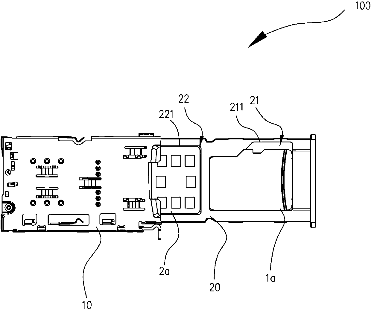
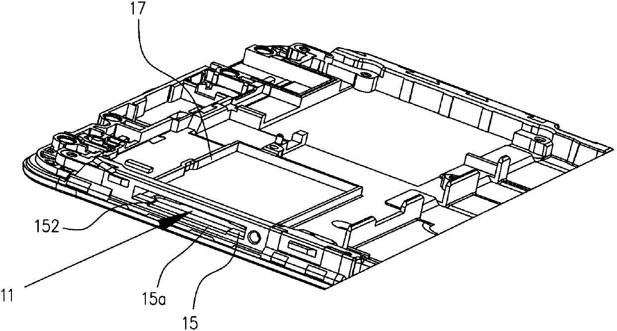
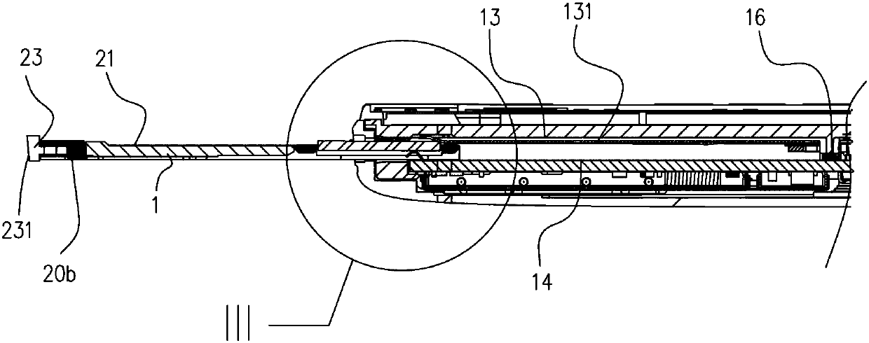
[0024] see Figure 1 to Figure 4 , the present invention provides a card insertion device 100 , the card insertion device 100 includes a card socket 10 and a card tray 20 . The card tray 20 is plugged into the slot 11 , and is slidably disposed on the bottom surface 14 along the extending direction of the bottom surface 14 . The card holder 20 is provided with a first card slot 21 and a second card slot 22 parallel to each other in the sliding direction, and the opening ends of the first card slot 21 and the second card slot 22 are all facing the The top surface 13 is described. The memory card 1 and the smart card 2 are placed in the first card slot 21 and the second card slot 22 respectively. When the card holder 20 is inserted into the slot 11 , the tops of the two first...


PUM


Abstract

The invention discloses a card seat, a card insertion device, and a mobile terminal. The card seat is used for the sliding fit with a card holder, and the card holder is sequentially provided with a first card slot and a second card slot in a sliding direction. The first card slot is used for accommodating a storage card, and the second card slot is used for accommodating an intelligent card. Thecard seat is provided with a slot, and the slot is provided with an opening. The slot is also provided with a top surface and a bottom surface opposite to the top surface. The top surface is providedwith two first bosses, and the two bosses are arranged at an interval. The opened end of the first card slot and the opened end of the second card slot face the top surface. When the card holder is inserted into the slot, the tops of the two bosses are used for pressing the edge of the intelligent card. The interval is used for allowing a storage card to pass, thereby guaranteeing that the storagecard and the intelligent card can be successfully inserted into the slot, and improving the stability of the card insertion device.

Description

technical field [0001] The invention relates to the field of electronic equipment, in particular to a card holder, a card insertion device and a mobile terminal. Background technique [0002] Most mobile phones on the market use an integrated card tray in which the smart card and the memory card are placed in the same tray. The existing integrated tray usually has a smart card slot at the front end and a memory card slot at the rear end. However, due to the thickness of the two cards Inconsistency, especially the back end of the memory card is equipped with a buckle structure, so that the thickness of the back end of the memory card is greater than the thickness of the smart card, so when the card tray is inserted and pulled out relative to the slot, in order to ensure that both cards can be pulled out or inserted smoothly Slot, the opening height of the slot is designed to be as large as possible, and after the card tray is inserted into the slot, there is still a gap betwe...

Claims


Application Information

Patent Timeline
Patent Type & Authority Applications(China)
IPC IPC(8): H01R13/502H01R13/629H01R27/02H01R12/71
CPCH01R12/714H01R13/502H01R13/629H01R27/02H01R2201/16
Inventor 付朝忠
Owner GUANGDONG OPPO MOBILE TELECOMM CORP LTD
Why Eureka
Try Eureka