
Extractor hood

A range hood and fan technology, applied in the field of range hoods, can solve the problems of easy blockage of the mesh, not convenient and simple, and limited grease separation effect, and achieve the effects of improving grease separation, reducing pollution, and good filtering effect

Inactive Publication Date: 2018-01-19
JOYOUNG CO LTD
View PDF8 Cites 3 Cited by
  • Summary
  • Abstract
  • Description
  • Claims
  • Application Information

AI Technical Summary

Problems solved by technology

[0002] The existing range hoods in the industry usually use oil nets to filter and separate the grease in the oil fumes. By designing the shape of the oil net (such as tower shape, cover shape, spherical shape, etc.), or the structure of the oil net (such as double-layer oil net , mesh structure, etc.) to achieve the separation of grease, because it is necessary to ensure the exhaust air volume of oil fume, it is necessary to design sufficient ventilation hole area on the oil net, once the mesh design of the ventilation hole is large, the separation effect on grease will be reduced If the mesh of the ventilation hole is designed to be smaller, although the grease separation effect can be improved, the mesh is easy to be blocked, and the user needs to disassemble the oil mesh for cleaning. In order to simplify the cleaning operation of the oil mesh, some manufacturers have added The filter cotton is installed inside or outside, and the filter cotton is used for grease separation, and the filter cotton is replaced after it is blocked. This method requires the user to pay attention to the use status of the filter cotton regularly, and then manually replace it. In summary, the above structure is very effective for grease separation. The effect is limited, and additional operation requirements are put forward for users, which is not convenient and concise enough

Method used


Image

  • Extractor hood
  • Extractor hood
  • Extractor hood

Examples


Embodiment 2

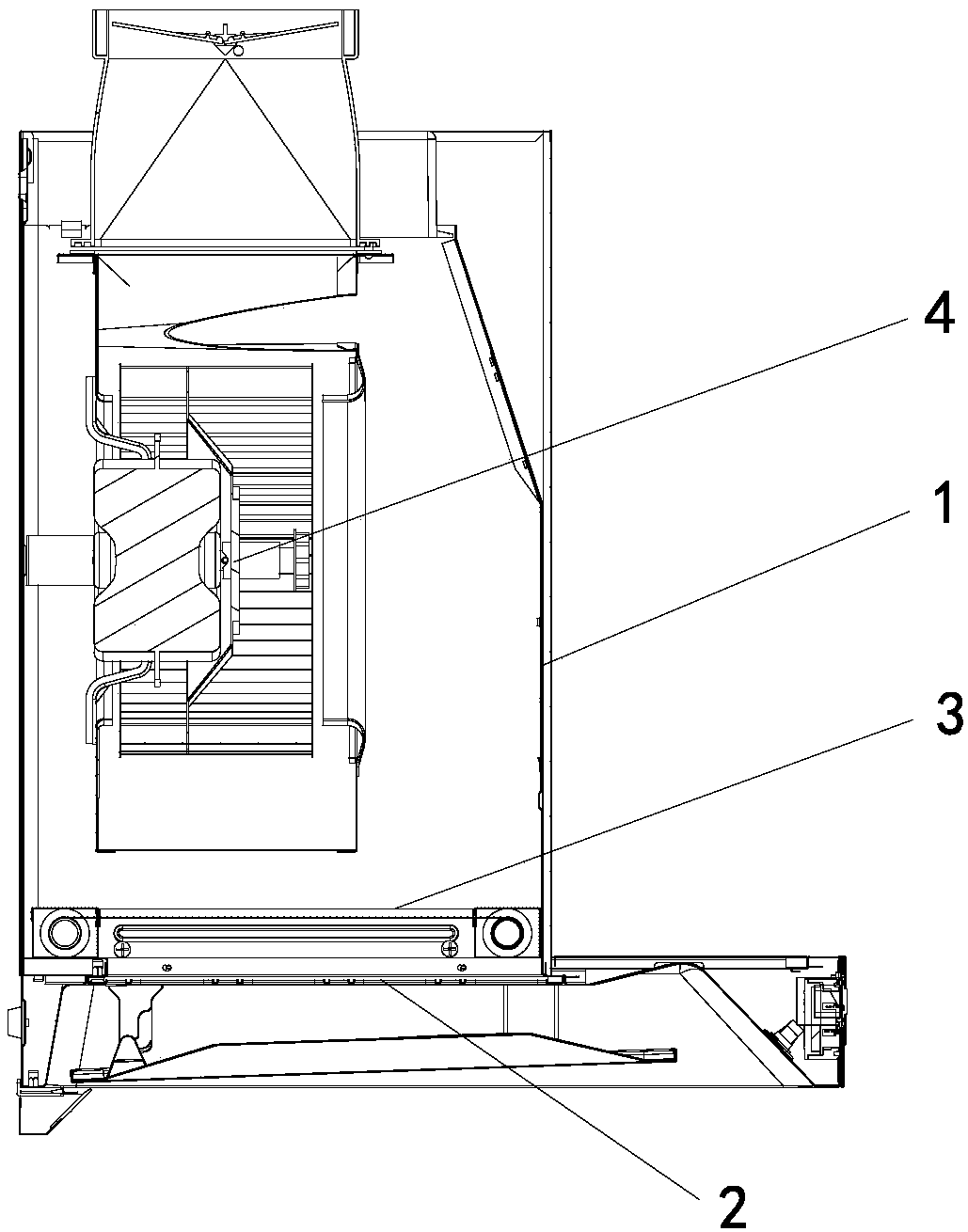
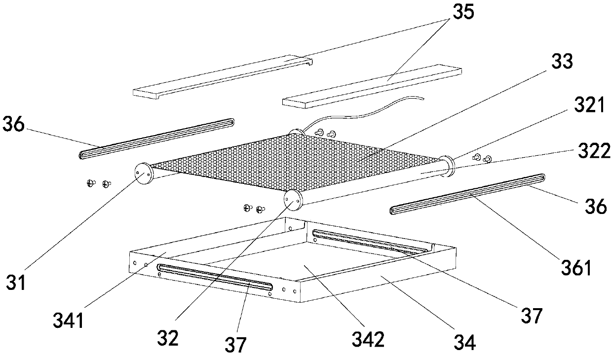
[0033] The difference between this embodiment and Embodiment 1 is that in this embodiment, the roller filter assembly 3 is applied to a side-suction range hood, the side-suction range hood is provided with an inclined smoke collection hood, and the smoke collection hood is provided with There is an installation plane for installing the roller filter assembly, and the roller filter assembly 3 is installed on the installation plane of the smoke collection hood; the air inlet 51 can be designed as a square, circular or other shapes, and the roller filter assembly 3 is installed At the front end of the air inlet, that is, the roller filter assembly 3 is installed on the outside of the installation plane of the smoke collecting hood. When the range hood smokes, the oil fume first passes through the flexible filter material 33 and then flows into the housing through the air inlet. In the example, since the air inlet is located at the rear end of the air inlet of the roller filter ass...


PUM


Abstract

The invention relates to an extractor hood. The extractor hood comprises a shell and a draught fan located in the shell. The shell is provided with an air inlet, and a roller type filter net assemblyis arranged in the shell and arranged at the position of the air inlet. The roller type filter net assembly comprises a tubular motor, a rotation pipe and a flexible filter material. The tubular motoris parallel to the axis of the rotation pipe. The flexible filter material is wound around the rotation pipe, one end of the flexible filter material is connected with the tubular motor, and the part, located between the tubular motor and the rotation pipe, of the flexible filter material shields the air inlet. According to the extractor hood, the grease separation degree is improved, electric replacing operation can be conducted on the roller type filter net assembly, the situation that a person manually detaches an oil net or other components for operation is not needed, and the extractor hood is simpler and more convenient.

Description

technical field [0001] The invention relates to the field of kitchen appliances, in particular to a range hood. Background technique [0002] The existing range hoods in the industry usually use oil nets to filter and separate the grease in the oil fumes. By designing the shape of the oil net (such as tower shape, cover shape, spherical shape, etc.), or the structure of the oil net (such as double-layer oil net , mesh structure, etc.) to achieve the separation of grease, because it is necessary to ensure the exhaust air volume of oil fume, it is necessary to design sufficient ventilation hole area on the oil net, once the mesh design of the ventilation hole is large, the separation effect on grease will be reduced If the mesh of the ventilation hole is designed to be smaller, although the grease separation effect can be improved, the mesh is easy to be blocked, and the user needs to disassemble the oil mesh for cleaning. In order to simplify the cleaning operation of the oil...

Claims


Application Information

Patent Timeline
IPC IPC(8): F24C15/20
Inventor 朱泽春赵沛彪
Owner JOYOUNG CO LTD
Learn More