
Pipe orifice deburring device

A technology of deburring and deburring mechanism, which is applied in the direction of grinding drive device, grinding workpiece support, grinding machine tool parts, etc., which can solve the problem of high labor intensity of the operator, low efficiency of manual deburring, and labor intensity of the operator. major issues

Inactive Publication Date: 2018-01-16
楚宗美
View PDF0 Cites 8 Cited by
  • Summary
  • Abstract
  • Description
  • Claims
  • Application Information

AI Technical Summary

Problems solved by technology

[0002] Pipe fittings are parts that connect pipes into pipelines. Pipe fittings are used in disciplines such as water conservancy technology, irrigation and drainage. In the manufacturing process of pipe fittings, it is required to deburr the pipe fittings. It is very long, and the labor intensity of the operator working for a long time is also very high. The efficiency of manual deburring is low, and it is difficult to keep up with the beat of the production line during online production. It is necessary to manually unload the pipe fittings and turn the pipe fittings, and deburr the other end of the pipe fittings. The turn-around takes a long time, and the long-term work is labor-intensive for the operator, which does not meet the needs of the market.

Method used


Image

  • Pipe orifice deburring device
  • Pipe orifice deburring device
  • Pipe orifice deburring device

Examples


Embodiment Construction

[0023] Below in conjunction with accompanying drawing and embodiment of description, specific embodiment of the present invention is described in further detail:

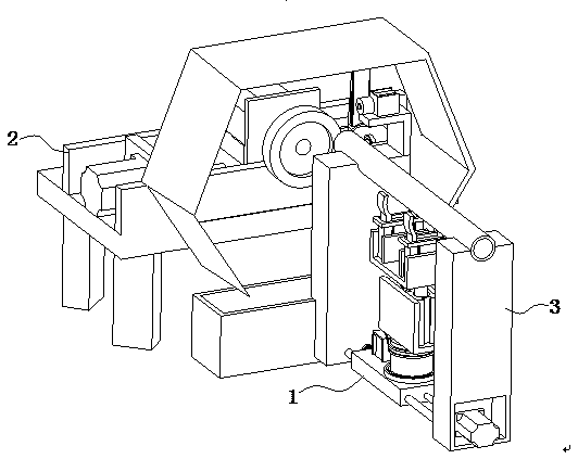
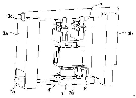
[0024] refer to Figure 1 to Figure 8 A pipe nozzle deburring device shown includes a head changing mechanism 1, a deburring mechanism 2 and a supporting device 3, and the supporting device 3 includes a left supporting column 3a and a right supporting column 3b arranged side by side , the head changing mechanism 1 includes a rotating assembly 4 located between the left supporting column 3a and the right supporting column 3b and a clamping assembly 5 located on the top of the rotating assembly 4, the left supporting column 3a and the right supporting column The top of the column 3b is provided with a groove 3c for storing workpieces, two grooves 3c are semicircular grooves 3c, and the two grooves 3c are coaxial, the rotating assembly 4 includes a rotating roller 4a and a The push assembly 6 on the top of the rotatin...


PUM


Abstract

The invention relates to the field of machining and in particular relates to a pipe orifice deburring device. The pipe orifice deburring device comprises a head-changing mechanism, a deburring mechanism and a supporting device, wherein the supporting device comprises a left supporting column and a right supporting column; the head-changing mechanism comprises a rotating assembly and a clamping assembly; grooves are formed in the tops of the left supporting column and the right supporting column; the rotating assembly comprises a rotary roller and a push assembly; a shifting assembly is arranged at the bottom of the rotary roller; the deburring mechanism comprises a clamping assembly and a deburring assembly; the deburring assembly comprises a supporting table and a sliding assembly; the sliding assembly comprises a left supporting plate and a right supporting plate; a second lead screw is arranged between the left supporting plate and the right supporting plate; a second lead screw sliding table is arranged on the second lead screw in a sleeving manner; and a first motor sleeving with a steel brush wheel is arranged on the top of the second lead screw sliding table. According to the pipe orifice deburring device disclosed by the invention, after deburring is completed at one end of a workpiece, the other end of the workpiece can be shifted out by the head-changing mechanism, time and labor can be saved, and the requirements in the market are met.

Description

technical field [0001] The invention relates to the field of mechanical processing, in particular to a deburring device for a nozzle of a pipe fitting. Background technique [0002] Pipe fittings are parts that connect pipes into pipelines. Pipe fittings are used in disciplines such as water conservancy technology, irrigation and drainage. In the manufacturing process of pipe fittings, it is required to deburr the pipe fittings. It is very long, and the labor intensity of the operator working for a long time is also very high. The efficiency of manual deburring is low, and it is difficult to keep up with the beat of the production line during online production. It is necessary to manually unload the pipe fittings and turn the pipe fittings, and deburr the other end of the pipe fittings. The turn-around takes a long time, and the long-term work is labor-intensive for the operator, which does not meet the needs of the market. Contents of the invention [0003] The object of...

Claims


Application Information

Patent Timeline
Patent Type & Authority Applications(China)
IPC IPC(8): B24B9/02B24B41/06B24B47/12B24B41/00
Inventor 楚宗美
Owner 楚宗美
Learn More