
Nanometer positioner for transmission electron microscope sample rods

A transmission electron microscope sample and locator technology, which is applied to the use of wave/particle radiation for material analysis, instruments, circuits, etc., can solve the problems of easy deformation of flexible silk claws, falling of probe clamping devices, and complicated relationships, etc., to achieve Simple and clear connection relationship, improved stability, and fewer parts

Inactive Publication Date: 2018-01-12
ZHEJIANG UNIV
View PDF0 Cites 17 Cited by
  • Summary
  • Abstract
  • Description
  • Claims
  • Application Information

AI Technical Summary

Problems solved by technology

[0004] However, the flexible claw is easy to deform. In order to maintain the friction between it and the ball, the shape of the flexible claw needs to be adjusted frequently
However, when the probe clamping device moves back and forth along the axial direction of the piezoelectric ceramic tube, the relationship between the shape of the flexible claw and the above-mentioned frictional force is complicated, and it is difficult to adjust its shape to ensure that the frictional force is always suitable
In addition, the probe clamping device is affected by gravity, which makes it easy to generate coupling motion during rough adjustment, and it is difficult to accurately control the probe
Even due to improper adjustment of the shape of the flexible wire claws, the ball cannot be grasped, and the probe holding device may fall into the inside of the equipment, resulting in equipment damage

Method used


Image

  • Nanometer positioner for transmission electron microscope sample rods
  • Nanometer positioner for transmission electron microscope sample rods
  • Nanometer positioner for transmission electron microscope sample rods

Examples


Embodiment Construction

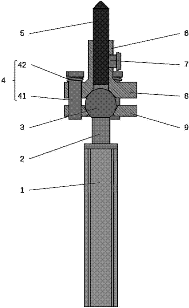
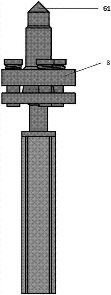
[0025] Such as figure 2 As shown, the nanopositioner used for the sample rod of the transmission electron microscope includes a sample rod head and a sample rod body, the sample rod head is used to load the sample, and the sample rod body is a piezoelectric ceramic tube 1;

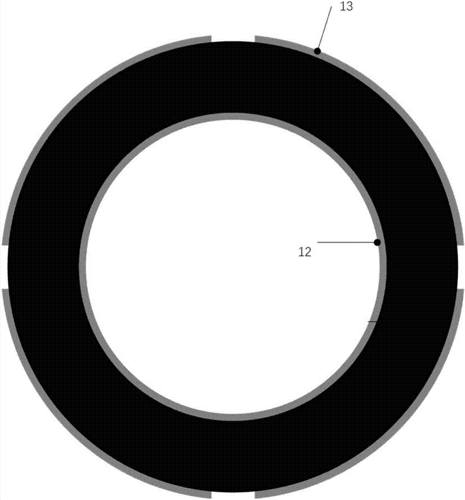
[0026] The circumferential wall of the piezoelectric ceramic tube 1 is evenly provided with a plurality of mutually independent conductive regions 13, and the head end of the piezoelectric ceramic tube 1 has a fixed joint ball 3, and the joint ball 3 is fixed on the head end of the ball seat 2, and the ball seat The end of 2 is fixed on the head end of piezoelectric ceramic tube 1. The piezoelectric ceramic tube 1 is a tubular member made of piezoelectric ceramic material, its inner wall surface 12 is completely covered by a conductive coating, and its outer wall surface is coated with a plurality of mutually insulated conductive coatings, and the mutually insulated conductive coatings form Conductive re...


PUM


Abstract

Disclosed is a nanometer positioner for transmission electron microscope sample rods. The nanometer positioner comprises a positioner head used for loading samples and a positioner body driving displacement of the samples; the positioner body is of a piezoelectric ceramic tube, conducting regions are arranged on the outer peripheral wall and the inner peripheral wall of the piezoelectric ceramic tube, multiple pairs of the conducting regions are arranged on the outer peripheral wall, and each paired conducting regions are symmetrical to the axis of the piezoelectric ceramic tube, the conducting regions on the outer peripheral wall are evenly arranged in a mutually independent manner, and a joint ball is fixed to the head end of the piezoelectric ceramic tube; the positioner head is mainlyformed by an upper pressing piece, a lower pressing piece and an elastic connection assembly, the joint ball is located between the upper pressing piece and the lower pressing piece, and each of the upper pressing piece and the lower pressing piece is provided with a slot matched with the joint ball. The nanometer positioner has the advantages of performance stability in reuse.

Description

technical field [0001] The invention relates to the field of transmission electron microscope accessories, in particular to a nanopositioner for a transmission electron microscope sample rod. Background technique [0002] In situ observation techniques have a long history in transmission electron microscopy research. By applying various physical effects on the sample and using a transmission electron microscope (TEM) to observe the changes in the microstructure and chemical state of the material, it is possible to directly study the performance of the material or device in the actual use process. For the performance of the material The research has important practical significance. The difficulty of in-situ technology in transmission electron microscopy lies in not only accurately applying physical effects on the sample, but also meeting a series of stringent conditions, such as maintaining the ultra-high vacuum of the electron microscopy system and ensuring extremely high ...

Claims


Application Information

Patent Timeline
IPC IPC(8): G01Q30/20G01Q10/00
CPCG01N23/2204G01N2223/07H01J37/20H01J2237/2007
Inventor 王宏涛张奕志
Owner ZHEJIANG UNIV
Learn More