
Machine vision detecting system for detecting defects of rolling roll grinding surface

A technology of machine vision detection and roll surface, which is applied in the direction of optical testing for flaws/defects, etc., can solve the problems of automatic detection, small effective measurement area, single imaging angle, etc., to eliminate adverse effects, uniform brightness distribution, and imaging clear effect

Inactive Publication Date: 2018-01-12
TSINGHUA UNIV +1
View PDF8 Cites 26 Cited by
  • Summary
  • Abstract
  • Description
  • Claims
  • Application Information

AI Technical Summary

Problems solved by technology

However, this method has some disadvantages: the surface array CCD camera is used to image the roll surface. Since the roll surface is a high-gloss cylindrical surface, there are serious reflection problems in the photos taken by the area array CCD camera, which makes the image quality poor and effective measurement The area is small; the light source and the camera are arranged on the same straight line, that is, the imaging angle is single, but in fact, for different defects, different lighting methods and angles are required to obtain better measurement results; the image formed by the camera is displayed on the monitor , the final defect identification still requires people to make judgments based on the photos, and complete automatic detection cannot be achieved

Method used


Image

  • Machine vision detecting system for detecting defects of rolling roll grinding surface
  • Machine vision detecting system for detecting defects of rolling roll grinding surface
  • Machine vision detecting system for detecting defects of rolling roll grinding surface

Examples


Embodiment Construction

[0039] The implementation method of the present invention will be described in detail below in conjunction with the accompanying drawings and embodiments. First of all, it should be pointed out that the following descriptions of the specific embodiments and examples of the present invention are intended to better explain the present invention, rather than limit the content of the present invention.

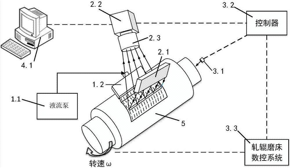
[0040] For this purpose, refer to figure 1 Shown specific embodiment, roll grinding surface defect machine vision detection system of the present invention comprises:

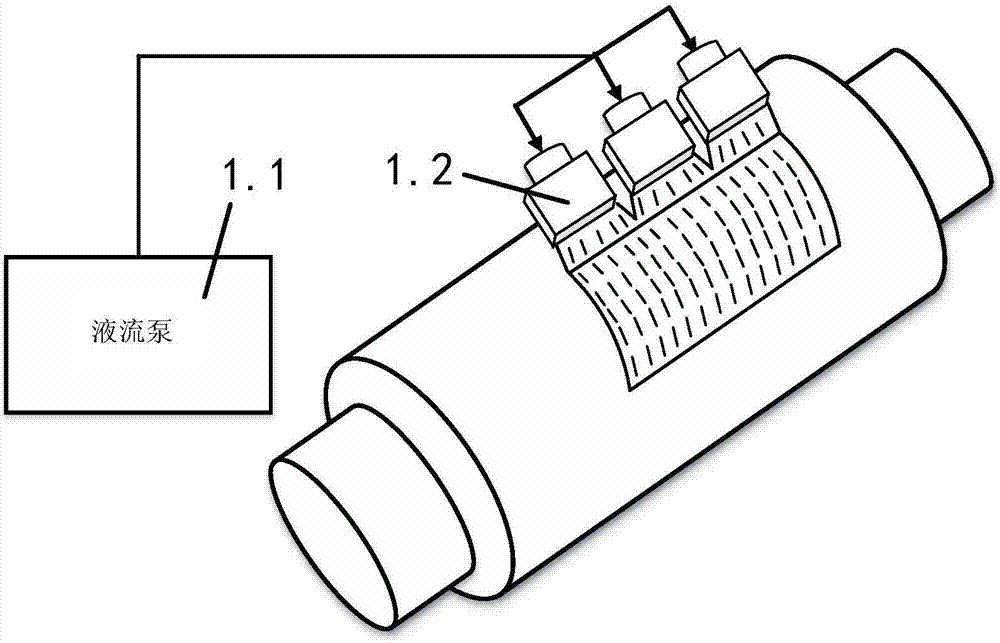
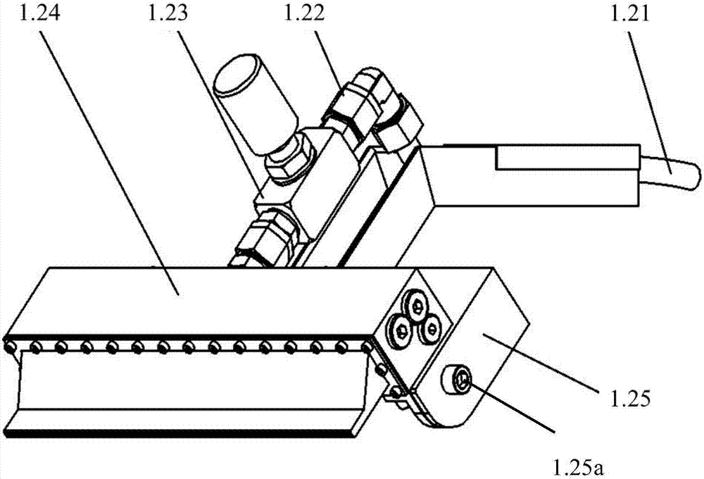
[0041] The cleaning device is set at 0-90 degrees to the normal direction of the surface of the tested roll 5, and the grinding liquid and grinding residues (such as broken abrasive grains and chips, etc.) on the surface of the tested roll after grinding are removed by spraying cleaning liquid. object), and form a uniform laminar liquid layer on the surface of the tested roll 5;

[0042] The image acquisition dev...


PUM


Abstract

The invention discloses a machine vision detecting system for detecting defects of a rolling roll grinding surface, belonging to the field of grinding processing surface defect detection. The system comprises a cleaning device, an image acquisition device, an image acquisition control unit and an image processing and analysis unit, wherein the cleaning device can be used for forming a uniform laminar flow liquid layer on the surface of a rolling roll to be detected; the image acquisition device is arranged around the rolling roll to be detected; the image acquisition control unit is respectively connected with the rolling roll to be detected and the image acquisition device; the image processing and analysis unit is electrically connected with the image acquisition device and is used for realizing defect classification identification, defect evaluation and over-limit alarm as well as fault diagnosis. The machine vision detecting system can be used for carrying out qualitative and quantitative detection on the defects such as short scratches, micro-vibration, spots, spiral patterns and reticulate patterns on the rolling roll grinding surface, overcomes the defects that the existingartificial naked eye detection method is high in subjectivity and lower in accuracy, easily causes inspection missing, can not realize quantitative detection, and the like, and improves detection efficiency, accuracy and reliability.

Description

technical field [0001] The invention belongs to the field of detection of surface defects in grinding, in particular to a machine vision detection system for surface defects of roll grinding. Background technique [0002] Roll grinding is a typical large-scale component grinding, and its grinding quality has high requirements on the stability of the grinding process, and the grinding is difficult. Short scratches, micro-vibrations, spots, spirals, reticulation, etc. are common defects on the grinding surface of rolls. These defects may be transferred to the rolled products during the rolling process, resulting in the degradation or even scrapping of the rolled products. It has an important impact on the production efficiency, product quality and stability of the production line. [0003] Since the common defect detection methods such as eddy current flaw detection and ultrasonic flaw detection cannot effectively detect the above defects, in actual production, the method of ...

Claims


Application Information

Patent Timeline
IPC IPC(8): G01N21/88
Inventor 杨军李学崑王立平曹宇中刘翔雄陈艳娟邹磊周玉娇杨之宾张云蒋昇
Owner TSINGHUA UNIV
Learn More