
A method of assembling a coupling

An assembly method and coupling technology, applied in the direction of couplings, elastic couplings, mechanical equipment, etc., can solve the problems of affecting work efficiency, long installation time, and many production processes, so as to enhance the overall stability and improve the The effect of using safety and improving the efficiency of changeover

Active Publication Date: 2021-03-02
GUANGXI YUCHAI MASCH CO LTD
View PDF5 Cites 0 Cited by
  • Summary
  • Abstract
  • Description
  • Claims
  • Application Information

AI Technical Summary

Problems solved by technology

The original coupling is characterized by simple manufacturing process, but the combined machine tool has a compact structure and limited operating space, and the end face of the coupling is facing the operator, and the hexagonal head of the screw cannot be seen, which makes it very difficult to install and disassemble the coupling. Disadvantages of long time
Combined machine tools process different models, and the coupling needs to be disassembled when changing the model. The number of changes is large, and the original coupling is difficult to install, which greatly affects the work efficiency.
Although the prior art also divides the coupling into two half-couplings for installation, its internal structure is relatively complicated and there are many production processes.

Method used


Image

  • A method of assembling a coupling
  • A method of assembling a coupling
  • A method of assembling a coupling

Examples


Embodiment Construction

[0019] The present invention will be further described in detail below in combination with specific embodiments and with reference to the accompanying drawings. It should be emphasized that the following description is only exemplary and not intended to limit the scope of the invention and its application.

[0020] Non-limiting and non-exclusive embodiments will be described with reference to the following drawings, wherein like reference numerals refer to like parts unless specifically stated otherwise.

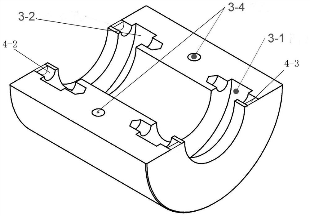
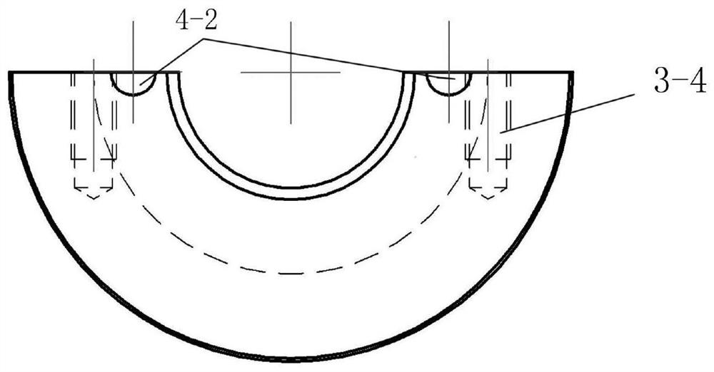
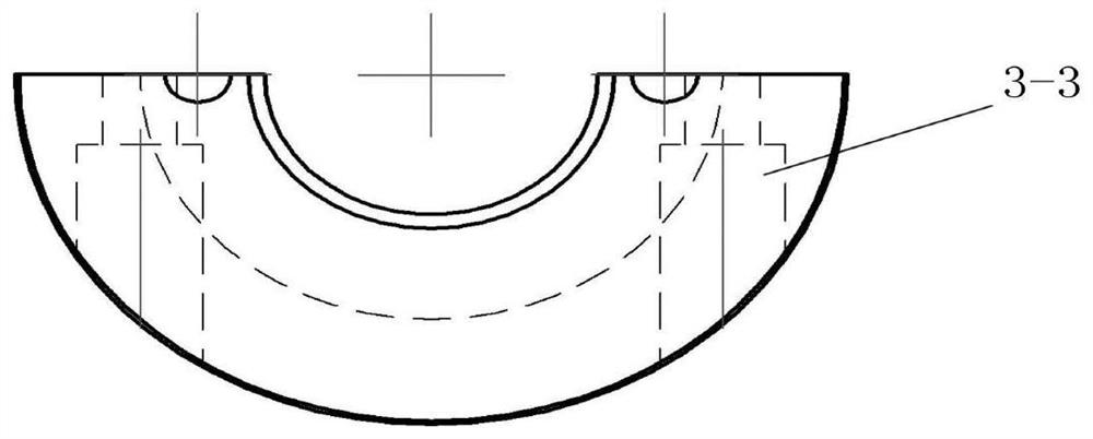
[0021] Such as Figure 1-6 As shown in a coupling, the middle part of the coupling 3 is provided with an axial inner hole, and the inner hole is a central through hole; the coupling 3 is evenly divided into the upper half coupling by a plane passing through its central axis, Coupling half. The upper half of the coupling is provided with a stepped hole 3-3, which is convenient for locking the countersunk head of the bolt 5, and the position of the lower half of the coupling...


PUM


Abstract

The invention discloses a coupler. An axial inner hole is formed in the middle of the coupler. The coupler is partitioned into an upper half coupler body and a lower half coupler body through a planepassing through the center axis of the coupler; the upper half coupler body and the lower half coupler body are detachably combined; the coupler further comprises a plurality of positioning pins, anda first annular clamping groove and a second annular clamping groove are formed in the inner wall of the inner hole of the coupler; and a plurality of axial pin holes matched with the positioning pinsin a one-to-one correspondence mode are formed in each of the two end surfaces of the coupler. The coupler provided by the invention is simple in structure, an operating space is expanded, front faces of screwheads can be clearly seen during dismounting, the coupler can be fast dismounted and mounted conveniently, and the remodeling efficiency is improved.

Description

technical field [0001] The invention relates to the technical field of shaft couplings, in particular to a shaft coupling assembly method for connecting a spindle of a boring-hinge combined machine tool. Background technique [0002] A coupling is a mechanical part used to connect two shafts (driving shaft and driven shaft) in different mechanisms to make them rotate together to transmit torque. At present, the shaft coupling connected to the mandrel of the boring-hinge machine tool is to use 12 M6*16 screws to pass through the flange surfaces of the two shafts, and tighten from both ends of the coupling to connect the two shafts. The characteristic of the original coupling is that the manufacturing process is simple, but the combined machine tool has a compact structure and limited operating space, and the end face of the coupling is facing the operator, and the hexagonal head of the screw cannot be seen, which makes it very difficult to install and disassemble the coupling...

Claims


Application Information

Patent Timeline
Patent Type & Authority Patents(China)
IPC IPC(8): F16D3/202
Inventor 梁敏杨政周荣林禄明
Owner GUANGXI YUCHAI MASCH CO LTD
Learn More