
Self-cleaning type sound barrier

A sound barrier and self-cleaning technology, which is applied in construction, noise absorption devices, etc., can solve the problems of poor pollutant removal effect, poor sound insulation effect of sound barrier, and difficult assembly and installation, so as to achieve good sound absorption effect, Simple structure, not easy to attach

Inactive Publication Date: 2018-01-12
广州市泰宇科技发展有限公司
View PDF7 Cites 5 Cited by
  • Summary
  • Abstract
  • Description
  • Claims
  • Application Information

AI Technical Summary

Problems solved by technology

Therefore, it is usually necessary to clean the sound barrier regularly. The traditional cleaning method is to use chemical agents to wipe, which not only consumes a lot of manpower and material resources, but also has poor pollutant removal effect.
[0003] In addition, the existing sound barriers are either simple in structure and poor in sound insulation, or complex in structure and difficult to assemble and install

Method used


Image

  • Self-cleaning type sound barrier
  • Self-cleaning type sound barrier
  • Self-cleaning type sound barrier

Examples


Embodiment 1

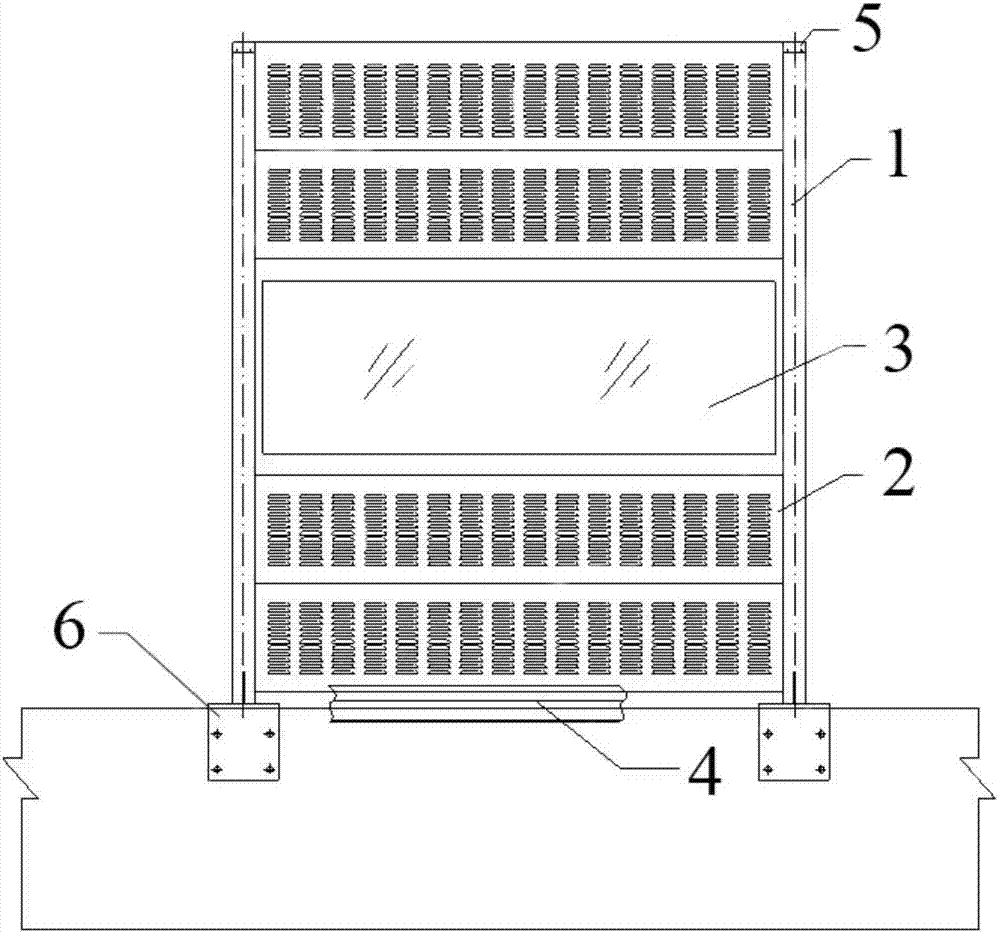
[0055] A self-cleaning sound barrier disclosed by the present invention comprises two parallel uprights 1, wherein a sound screen plate is arranged between the two uprights, and the side of the upright 1 facing the sound screen plate is provided with a 1. A card slot opened in the length direction, and the side of the sound screen plate is locked in the card slot.

[0056] The surface of the column and the sound screen plate is coated with a nano-titanium dioxide photocatalyst coating.

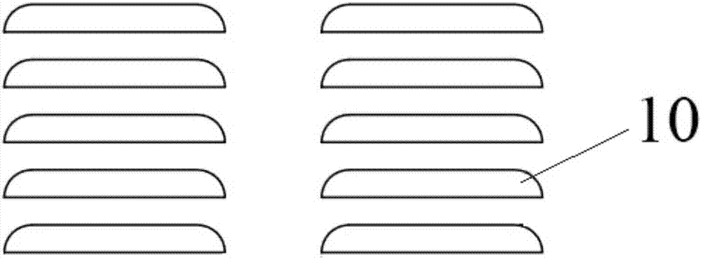
[0057] The surface of the base material 9 of the self-cleaning sound barrier includes: the outer surface of the column 1, the front and rear panels 11 of the sound absorption screen 2, the surface of the sound insulation screen 3 and the outer surface of the window frame and the lower cover plate 4 are coated with nano-titanium dioxide Photocatalyst coating.

[0058] The nano-titanium dioxide photocatalyst coating includes a silicon-containing intermediate layer 8 and nano-TiO 2 Self-cleanin...

Embodiment 2

[0075] The difference between the self-cleaning sound barrier disclosed in this embodiment and the previous embodiment is that the sound-absorbing screen 2 is installed between the two columns 1, and the sound-insulating screen 3 and the window frame are no longer installed, so that not only the self-cleaning sound barrier can be added The contact area with the sound wave increases the attenuation rate of the sound wave, shortens the process of absorbing the sound wave, and enhances the sound insulation effect of the sound barrier. Moreover, the overall structure is integrated, the structure is simple, and the assembly is convenient. The construction cost maximizes the use of social resources, which is in line with the scientific development concept and the central spirit of building a conservation-oriented society; an upper cover is installed above the self-cleaning sound barrier to protect the lower sound-absorbing screen 2 from the upper The impact of the environment can avo...


PUM

PropertyMeasurementUnit
Thicknessaaaaaaaaaa

Abstract

The invention belongs to the technical field of noise abatement, and particularly relates to a self-cleaning type sound barrier. The sound barrier comprises at least two vertical columns which are arranged in parallel. At least one sound barrier plate block is arranged between every two adjacent vertical columns, and the two side edges of each sound barrier plate block are fixed to the vertical columns correspondingly, and the sound barrier is characterized in that the surfaces of the vertical columns and / or the sound barrier plate blocks are coated with nano titanium dioxide photocatalyst coatings, the sound barrier can be maintained to be clean by being washed with normal clean water or rainwater, thus the self-cleaning effect is achieved. Meanwhile, the organics exhausted by a car canbe degraded to some extent, and an environmental protection function is achieved at the same time.

Description

technical field [0001] The invention belongs to the technical field of noise control, in particular to a self-cleaning sound barrier. Background technique [0002] The use of sound barriers is very wide, and it is mainly used in sound insulation and noise reduction places for noise sources such as railways, expressways and elevated composite roads. We often find that after a period of use, some more stubborn organic pollutants will adhere to the sound barrier, most of which come from vehicle exhaust emissions, smoke and other polluting particles in the air. Therefore, it is usually necessary to clean the sound barrier regularly. The traditional cleaning method is to use chemical agents to wipe, which not only consumes a lot of manpower and material resources, but also has poor pollutant removal effect. [0003] In addition, the existing sound barriers are either simple in structure and poor in sound insulation effect, or complex in structure and difficult to assemble and in...

Claims


Application Information

Patent Timeline
IPC IPC(8): E01F8/00
Inventor 单泰雷
Owner 广州市泰宇科技发展有限公司
Learn More