Heavy-load ultra-low limit shear-fork-type hydraulic lift and working method thereof
An ultra-low limit, lift technology, applied in the direction of lifting frame, lifting device, etc., can solve the problem of insufficient lifting force in the compression stage, and achieve the requirements of improving system stability and carrying capacity, reducing mechanical stiffness, and strong system stability Effect
- Summary
- Abstract
- Description
- Claims
- Application Information
AI Technical Summary
Problems solved by technology
Method used
Image
Examples
Embodiment 1
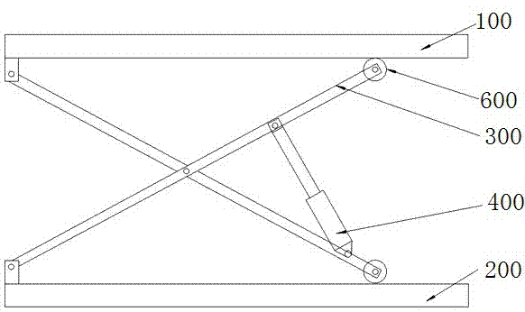
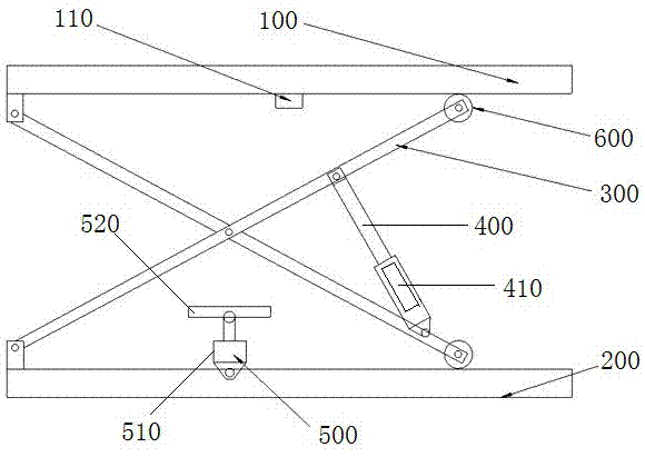
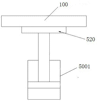
[0021] Embodiment 1: as Figure 2~3 As shown, a heavy-duty ultra-low limit scissor hydraulic lift includes a stage 100 and a base 200 located below the stage 100, and a pair of scissor arms 300 is arranged between the stage 100 and the base 200. The center of the scissor arm 300 is hingedly connected. The upper and lower ends on the left side of the scissor arm 300 are respectively hinged on the stage 100 and the base 200 , and the upper and lower ends on the right side slide up with the stage 100 and the base 200 respectively through rollers 600 The two arms of the scissor arm 300 are provided with a main propulsion hydraulic cylinder 400 that drives the scissor arm 300 to open and close. The cylinder body of the cylinder 400 is provided with an inclinometer 410 for sensing the angle between the main propulsion hydraulic cylinder and the horizontal direction. The auxiliary lifting system 500 of the object table 100; the angle α between the main propulsion hydraulic cylinder ...
Embodiment 2
[0025] Embodiment 2: as Figure 4 As shown, the difference between this embodiment and Embodiment 1 is that the driving mechanism is different. In this embodiment, the driving mechanism includes a screw rod 5002 whose upper end supports the auxiliary platform. The driven bevel gear 5003 has a driving bevel gear 5004 meshing with it beside the driven bevel gear, and the driving bevel gear 5004 is driven by an electric motor or a hydraulic motor.
Embodiment 3
[0026] Embodiment 3: as Figure 5 As shown, the difference between this embodiment and Embodiment 1 is that the driving mechanism is different. In this embodiment, the driving mechanism includes a screw rod 5002 whose upper end supports the auxiliary platform. The worm wheel 5005 has a worm 5006 engaged with it beside the worm wheel, and the worm 5006 is driven by an electric motor or a hydraulic motor.
PUM
 Abstract
Description
Claims
Application Information
 - R&D
- Intellectual Property
- Life Sciences
- Materials
- Tech Scout
- Unparalleled Data Quality
- Higher Quality Content
- 60% Fewer Hallucinations
Browse by: Latest US Patents, China's latest patents, Technical Efficacy Thesaurus, Application Domain, Technology Topic, Popular Technical Reports.
© 2025 PatSnap. All rights reserved.Legal|Privacy policy|Modern Slavery Act Transparency Statement|Sitemap|About US| Contact US: help@patsnap.com


