
Electronic accelerator pedal assembly

An electronic accelerator pedal and assembly technology, applied in the field of auto parts, can solve the problems that the precision and sensitivity of mechanical motion transmission cannot meet a high requirement, the accelerator pedal assembly cannot realize the precise control of the accelerator, and the accelerator pedal is slow to reset. Achieve the effect of improving pitting potential, reducing weight and fast reset speed

Active Publication Date: 2018-01-09
NINGBO GAOFA AUTOMOTIVE CONTROL SYSTEM CO LTD
View PDF11 Cites 3 Cited by
  • Summary
  • Abstract
  • Description
  • Claims
  • Application Information

AI Technical Summary

Problems solved by technology

As we all know, the transmission accuracy and sensitivity of mechanical motion cannot meet a very high requirement, so the traditional accelerator pedal assembly cannot achieve the technical purpose of precise accelerator control; on the other hand, after the accelerator pedal is pressed down, the traditional The accelerator pedal resets slowly, which brings inconvenience to driving. The accelerator pedal needs to be pressed continuously during use, which will cause the accelerator pedal to wear

Method used


Image

  • Electronic accelerator pedal assembly
  • Electronic accelerator pedal assembly
  • Electronic accelerator pedal assembly

Examples


Embodiment 4

[0034] The composition of this embodiment and embodiment 3 is the same, the difference is that the surface of this embodiment contains a co-infiltration layer, and the co-infiltration process of the co-infiltration layer is:

[0035] First use 1000-mesh sandpaper to polish the surface, then wash it with degreasing agent and water for 10 minutes, and then dry it;

[0036] Seal the dried electronic accelerator pedal and co-infiltration agent together into the infiltration tank, put it into a heating furnace, raise the temperature to 950°C, and co-infiltrate for 4 hours.

[0037] The co-penetrating agent is a mixture of ferroboron and ferrotitanium.

Embodiment 5

[0039] The difference between this embodiment and Embodiment 4 is that the co-infiltration agent also includes a chromium donor, and the chromium donor is ferrochrome.

Embodiment 6

[0041] The difference between this embodiment and embodiment 5 is that the co-penetration agent also includes the activator potassium fluoroborate.


PUM


Abstract

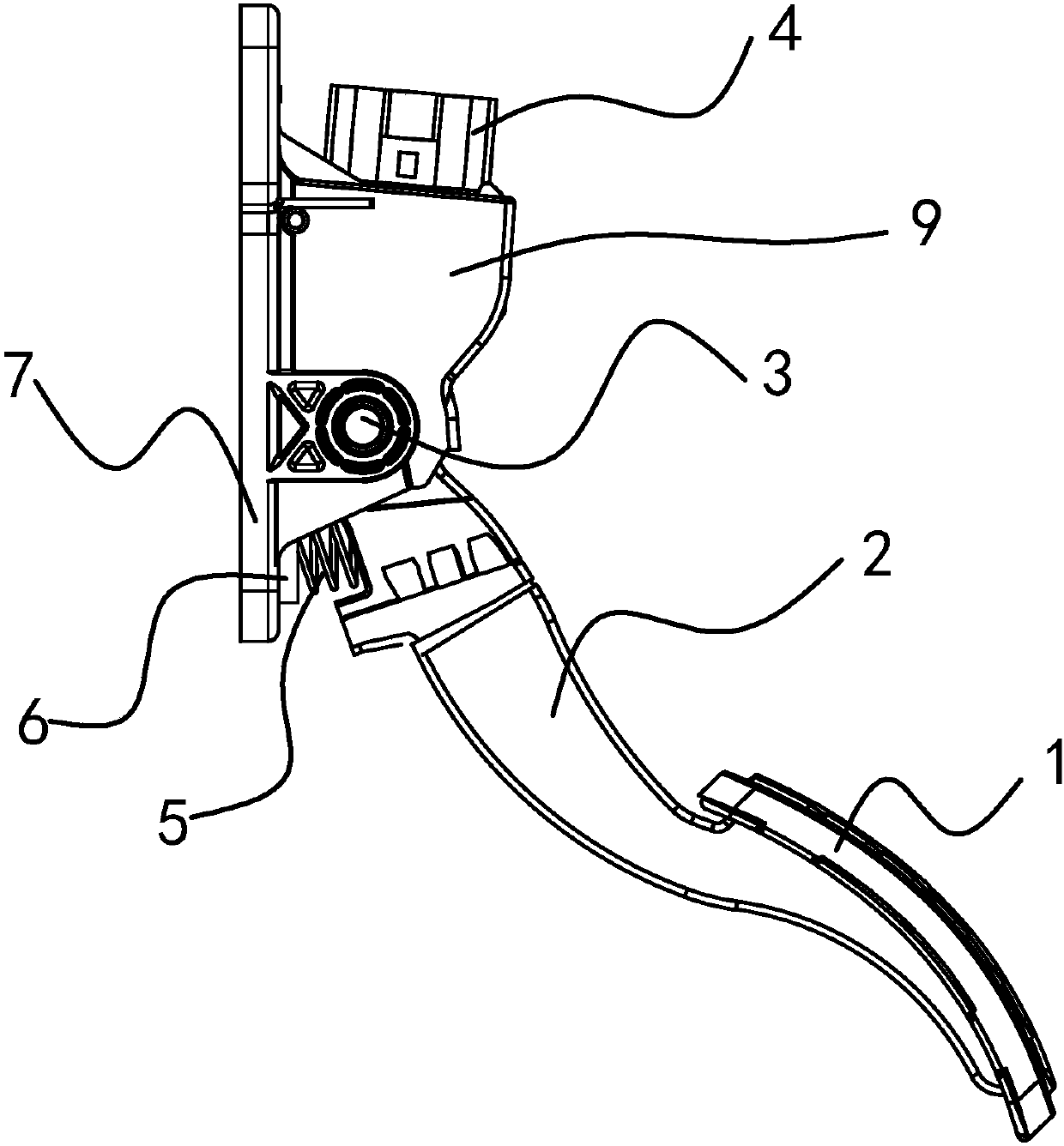
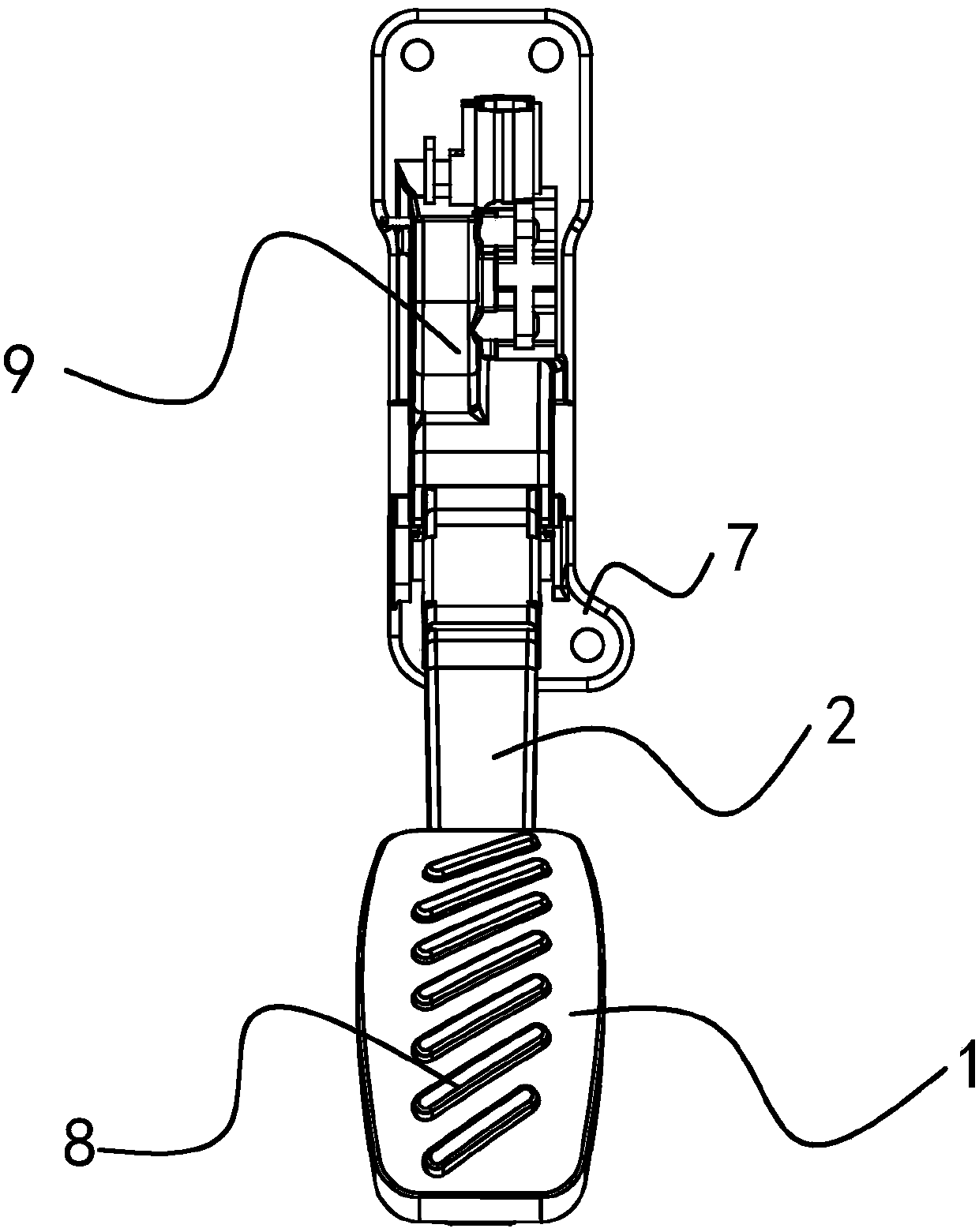
The invention provides an electronic accelerator pedal assembly and belongs to the technical field of car parts. According to the electronic accelerator pedal assembly, the problems that an existing electronic accelerator pedal assembly is complex in structure, not resistant to abrasion, poor in transmission effect and low in sensitivity are solved. The electronic accelerator pedal assembly comprises a base, and the base is composed of the components of, by weight, 1-1.3% of C, 0.8-1% of Si, 0.7-0.8% of Mn, 0.02-0.03% of P, 0.1-0.2% of S, 16-20% of Cr, 0.3-0.4% of Ti, 0.3-0.5% of Nb, 0.5-0.6%of Mo, 0.1-0.2% of Ce, 0.1-0.2% of La and the balance Fe. The base further comprises a co-diffusion coating, is internally provided with an electronic induction part and is further provided with a pedal shaft. The pedal shaft is sleeved with a rotary shaft sleeve, a pedal is assembled on the rotary shaft sleeve, and the base comprises a bottom plate. A cylindrical spring seat is arranged on the bottom plate, a reset spring is fixedly mounted in the spring seat, the reset spring is arranged perpendicular to the bottom plate, and the other end of the reset spring is fixed to the rotary shaft sleeve. The electronic accelerator pedal assembly has the advantages of being simple in structure and high in sensitivity.

Description

technical field [0001] The invention relates to the technical field of auto parts, in particular to an electronic accelerator pedal assembly. Background technique [0002] Accelerator pedal is an auto part to be controlled when the car accelerates. It can control the oil intake of the motor vehicle cylinder and then control the speed and power of the engine, and finally realize the control of the speed of the motor vehicle. Most of the traditional accelerator pedal assemblies realize accelerator opening control through connecting rods or cables, and a series of actions are mechanical movements. As we all know, the transmission accuracy and sensitivity of mechanical motion cannot meet a very high requirement, so the traditional accelerator pedal assembly cannot achieve the technical purpose of precise accelerator control; on the other hand, after the accelerator pedal is pressed down, the traditional The accelerator pedal resets slowly, which brings inconvenience to driving....

Claims


Application Information

Patent Timeline
Patent Type & Authority Applications(China)
IPC IPC(8): B60K26/02C23C12/02C22C38/60C22C38/28C22C38/26C22C38/22C22C38/02C22C38/04
Inventor 钱高法
Owner NINGBO GAOFA AUTOMOTIVE CONTROL SYSTEM CO LTD
Learn More