
STEREOLlTHOGRAPHY MACHINE WITH IMPROVED OPTICAL UNIT

A stereo light curing, optical unit technology, applied in optical components, optics, opto-mechanical equipment, etc., can solve the problem of mirror size limitation, low production time, large inertial momentum, etc.

Inactive Publication Date: 2018-01-02
埃托雷毛里齐奥科斯塔贝伯
View PDF3 Cites 5 Cited by
  • Summary
  • Abstract
  • Description
  • Claims
  • Application Information

AI Technical Summary

Problems solved by technology

The moment of inertia of such a mirror is too great to move at a relatively high speed
This makes production time low
In addition, dual-axis MOEMS mirrors have an inherent limitation on the size of the mirror itself, since the mirror must move about the two axes of incidence
Therefore, the size of the laser spot is also restricted, increasing the cost of the stereolithography molding machine

Method used


Image

  • STEREOLlTHOGRAPHY MACHINE WITH IMPROVED OPTICAL UNIT
  • STEREOLlTHOGRAPHY MACHINE WITH IMPROVED OPTICAL UNIT
  • STEREOLlTHOGRAPHY MACHINE WITH IMPROVED OPTICAL UNIT

Examples


Embodiment Construction

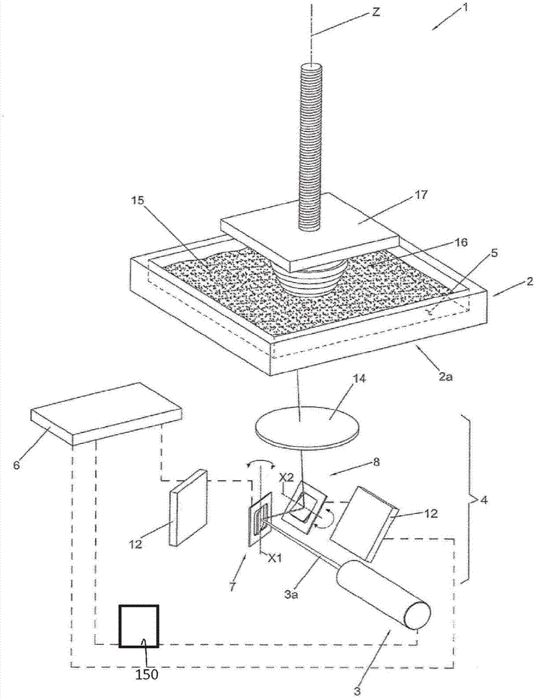
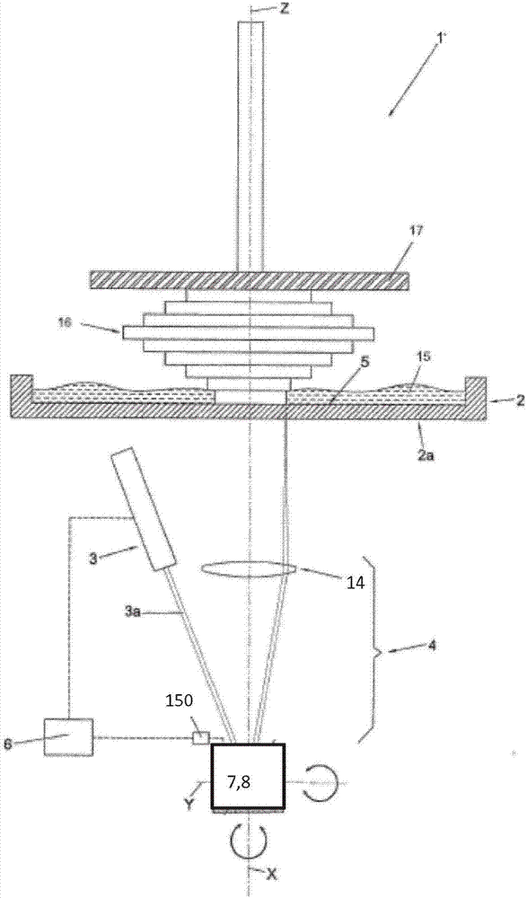
[0082] The stereolithography machine that is the subject of the present invention, in figure 1 and image 3 In the whole, it is represented by 1, and can be stacked by multiple layers ( image 3 The process seen in ) produces a three-dimensional object 16, said layers being obtained by selectively exposing a fluid substance 15 to predetermined radiation 3a suitable for curing it.

[0083] Preferably, the fluid substance 15 is a photosensitive liquid resin. Preferably, the resin is a polymeric resin curable using radiation in the UV range. Preferably, the resin comprises:

[0084] (Meth)acrylated monomers and / or oligomers further comprising photosensitizers and / or colorants and, in some cases, fillers.

[0085] Radiation for exposing the fluid substance is emitted by the laser source 3, preferably radiation in the wavelength range of violet wavelengths (eg 405nm±10nm). When a laser beam of a given irradiance hits the resin, the above-mentioned resin is solidified. Prefera...


PUM


Abstract

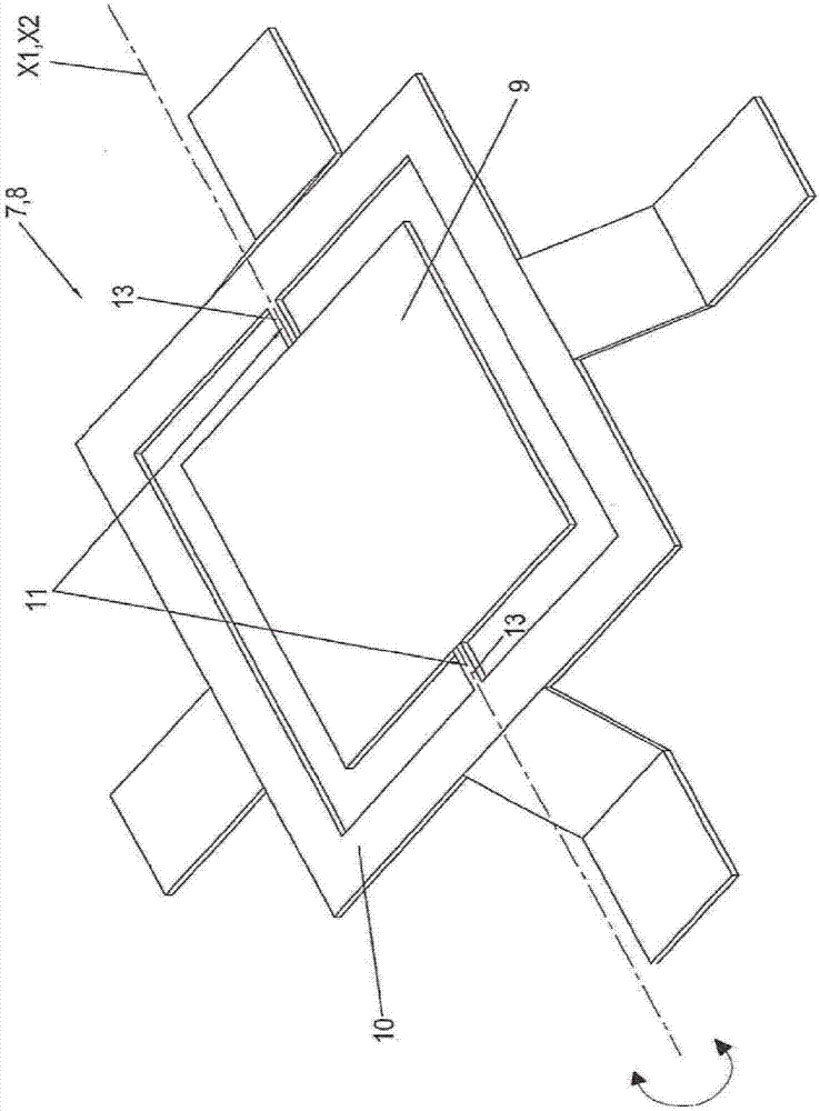
The invention relates to a Stereolithography machine (1) comprising: a container (2) for a fluid substance (15) suited to be solidified through exposure to predefined radiation (3a); a laser source (3) apt to emit a beam of said predefined radiation (3a); a vector scanning optical unit (4) configured to perform a vector scanning of a reference surface (5) arranged inside said container (2) according to a desired vector data image by means of said predefined radiation; a memory to store said vector data image representative of an image to be scanned on said reference surface; a logic control unit (6) configured for controlling said vector scanning optical unit (4) and / or said laser source (3) in such a way as to expose a predefined portion of said reference surface (5) to said radiation (3a) according to said vector data image; wherein said vector scanning optical unit (4) comprises a first and a second micro- opto-electromechanical systems (MOEMS) (7, 8) arranged in series one after the other with respect to a travelling path of said predefined radiation, each MOEMS system comprising: a mirror (9) having a diameter comprised between about 2 mm and about 8 mm associated with a supporting structure (10) through articulation means (11) configured so as to define for said mirror (9) a rotation axis (X1, X2); an actuator (12) suited to move said mirror (9) around said rotation axis(X1, X2) in a quasi-static manner at an angular speed so that a corresponding marking speed of said laser beam on said reference surface (5) is comprised between about 0.5 m / s and about 3 m / s when said laser source (3) is emitting said predetermined radiation (3a) during said vector scanning; and wherein the rotation axis (X1) of the mirror (9) of the first MOEMS system (7) is incident to the rotation axis (X2) of the mirror (9) of the second MOEMS system (8).

Description

technical field [0001] The invention relates to a stereolithography machine suitable for the manufacture of three-dimensional objects by means of a plurality of overlapping layers, each layer being obtained by selective solidification of a fluid substance in an area corresponding to the volume of the object to be manufactured . Background technique [0002] Stereolithography machines of known type comprise a container in which there is a fluid substance, usually photosensitive resin in liquid or pasty state. [0003] The machine also includes a source, which is generally of the luminescent type and which emits radiation suitable for solidifying the fluid substance. The optical unit serves to deliver said radiation towards a reference surface arranged in the container, which reference surface corresponds to the position of the layer of the object to be solidified. [0004] The three-dimensional object being formed is supported by a form plate which is vertically movable rel...

Claims


Application Information

Patent Timeline
IPC IPC(8): B29C64/268B29C64/135B29C64/20B33Y30/00
CPCG02B26/08G02B26/101B29C64/135B29C64/268B29C64/277B33Y30/00B33Y50/00B29C64/393B29C64/20B33Y50/02B29K2105/0002G02B26/0833G03F7/70416G05B19/4099G05B2219/49023
Inventor 埃托雷·毛里齐奥·科斯塔贝贝尔
Owner 埃托雷毛里齐奥科斯塔贝伯
Learn More