Modular manufacturing multi-purpose winding-type vacuum coating machine

A vacuum coating machine, multi-purpose technology, applied in vacuum evaporation coating, sputtering coating, ion implantation coating, etc., can solve the problems of limited film production, high dust pollution, poor atmosphere isolation, etc.

Pending Publication Date: 2017-12-26
惠州市烯谷新能源产业技术研究院有限公司
View PDF0 Cites 2 Cited by
  • Summary
  • Abstract
  • Description
  • Claims
  • Application Information

AI Technical Summary

Problems solved by technology

[0004] The winding mechanisms used in conventional winding vacuum coating equipment are mostly single chamber or multi-chamber. For single chamber equipment, its structural characteristics are: a. It includes a sealed vacuum container (circular or rectangular chamber) ; b. A metal partition is used to isolate an unwinding area, a coating area, and a winding area in the container; c. It has the advantages of compact design, small footprint, and low cost; d. The disadvantage is that each area Poor atmosphere isolation, more dust pollution during work, limited production film system, low production capacity, etc.
For multi-cavity equipment, its disadvantages are the production of single-coated main hub, limited production film system, single product variety, equipment can only be customized according to the process, and the manufacturing cost is high.
[0005] The above-mentioned equipment structure design is the commonly used winding-type vacuum coating equipment at present. The design and manufacture of the equipment are all special equipment that must be independently designed on the basis of prior determination of the product process. They can only coat single-sided film-forming products. When producing double-sided coating products, it is necessary to turn over the coating (foil material) for secondary processing, which has the disadvantages of low yield and low production efficiency; when producing simple film products, low equipment utilization rate and other defects

Method used


Image

  • Modular manufacturing multi-purpose winding-type vacuum coating machine
  • Modular manufacturing multi-purpose winding-type vacuum coating machine
  • Modular manufacturing multi-purpose winding-type vacuum coating machine

Examples


Embodiment 1

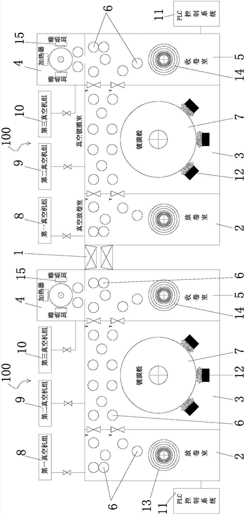
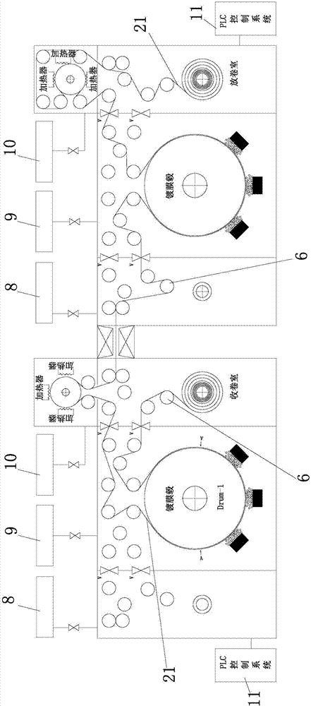
[0033] Embodiment 1, reference Figure 1 to Figure 3 As shown, a modular manufacturing multi-purpose roll-to-roll vacuum coating machine includes two vacuum roll-to-roll coating system units 100, the two vacuum roll-to-roll coating system units 100 are connected by a vacuum coupling valve 1, and the roll to be coated The material 21 passes through the vacuum connection valve 1 and enters the next empty winding coating system unit 100; the vacuum winding coating system unit 100 includes an unwinding chamber 2, a coating chamber 3, a heat treatment chamber 4 and a winding chamber 5, all of which are There are several spools 6 that can be used for tensioning, conveying the coil material to be coated, and changing the winding direction of the coil material to be coated. The coating chamber 3 is provided with a coating hub 7. After coating one side in the roll-to-roll coating system unit, the other side is coated in the next vacuum roll-to-roll coating system unit because the reel ...


PUM


Abstract

The invention provides a modular manufacturing multi-purpose winding-type vacuum coating machine. The modular manufacturing multi-purpose winding-type vacuum coating machine comprises at least two vacuum winding coating system units. The two adjacent vacuum winding coating system units are connected through a vacuum coupling valve. A roll material to be coated passes through the vacuum coupling valve and goes into the next empty winding coating system unit. Each vacuum winding coating system unit comprises an unwinding chamber, a coating chamber, a heat treatment chamber and a winding chamber which are each provided with a plurality of reels used for tensioning and conveying the roll material to be coated and changing the winding direction of the roll material to be coated. Each coating chamber is provided with a coating hub. After one surface of the roll material to be coated is subjected to coating in the previous vacuum winding coating system unit, the winding direction of the roll material to be coated is changed through the reels, and the other surface of the roll material to be coated is subjected to coating in the next vacuum winding coating system unit.

Description

technical field [0001] The invention relates to the industries of vacuum coating, capacitor film manufacturing and photoelectric display film manufacturing, and realizes single / double-sided coating for flexible film materials, in particular to a modular manufacturing multi-purpose winding vacuum coating machine. Background technique [0002] Vacuum coating is a kind of plasma technology application, that is, in a vacuum environment, the magnetron sputtering cathode with the material to be plated is ignited (the resistance evaporation method is to heat the film material crucible), the magnetron cathode generates plasma, and high-energy ions The particles to be coated are sputtered out by bombarding the target surface (film material), and the sputtered particles are deposited on the workpiece to be plated to form a simple film, a compound film, etc. [0003] Roll-to-roll vacuum coating technology is widely used in the field of functional and decorative film manufacturing of fl...

Claims


Application Information

Patent Timeline
IPC IPC(8): C23C14/35C23C14/56C23C14/54
CPCC23C14/352C23C14/54C23C14/562
Inventor 赵斌
Owner 惠州市烯谷新能源产业技术研究院有限公司
Why Eureka
Try Eureka